

Manufacturing processes are quite complex, and the choice of a production method is directly related
Learn More →
The symbols depicting surface finish are significant in the quality control of various machine components in the engineering and manufacturing sectors. It is their quality, function, and beauty that determine their value. This manual explains the surface finish notations and standards, focusing on their practical uses and the intricate language these symbols could employ. Readers will become familiar with different industries’ norms, measuring procedures, and surface finish definitions. This article will prepare you to understand the consequences surface finish specifications have on the performance, life span, and manufacturability of designed components. This guide is helpful for engineers, designers, and product inspectors since it enables them to understand and use surface finish standards proficiently.
A Surface Finish Symbol on engineering drawings is a specific mark to describe surface finish, including texture, roughness, or the machining process used on the surface. These symbols provide critical information regarding the levels of workmanship or surface treatment necessary to achieve a required function or aesthetic feature. This information can include roughness values (Ra), machining allowances, and processes to be applied, hence unambiguously disambiguating the designers, manufacturers, and quality controllers. The achievement of efficiency in production and compliance with required engineering specifications is enhanced through correctly using these symbols.
Surface finish is the texture or smoothness of a manufactured surface, depending on the method used to make it and any later treatments. It also considers the measurement of surface irregularities, including the height of the rough peaks and the depths of the valleys, which affect the part’s performance and functionality. Aspects such as wear resistance, lubrication, fatigue strength, and assembly fit are greatly influenced by surface finish, which is why it needs to be optimal.
Key Technical Parameters For Surface Finish
Roughness (Ra): Average deviation of the surface profile from the mean line, usually expressed in micrometers (µm) or microinches.
For machined parts, the typical value is within the limits of 0.8 – 6.3 µm.
For polished or precision surfaces: 0.05 – 0.4 µm.
Waviness (W): Irregularities of larger magnitude and more prolonged than average spacing presented in the surface affect the ability to seal and misalign.
Lay: The primary alignment of the surface features is sometimes given to satisfy functional purposes.
Processing Methods: To obtain the specified finish, methods such as turning, grinding, polishing, or coating may be suggested.
In understanding and subsequently detailing these technical parameters, the desired intent of purpose, effectiveness, and performance of a particular part can be ensured with certainty.
Symbols for surface finish refer to drawings and documents’ notations of specialized needs that surface treatment adds to the finishing touch of a given component. Such symbols help engineers and machinists quickly decipher what surface texture is needed and the steps that should be taken to achieve it. Here are some symbols and their definitions:
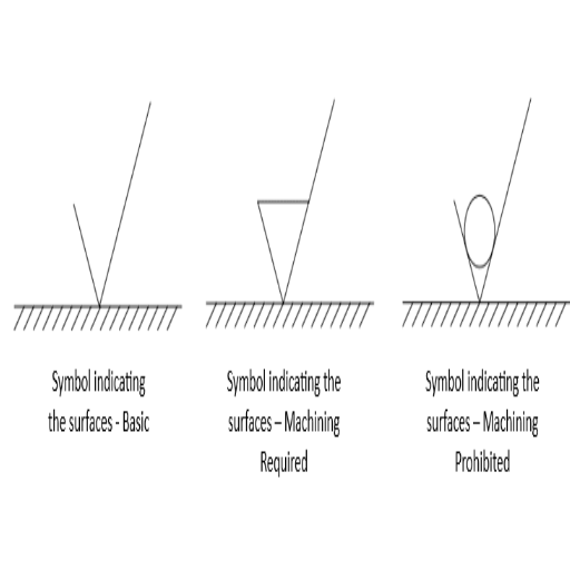
Basic Surface Finish Symbol ( — )
It demonstrates that the surface would be machined or finished.
Specific parameters are not described unless additional symbols or numbers are specified.
Machining Required ( √ )
It shows that surface finish requires modification to achieve the necessary material.
Roughness values or additional measurement symbols about the finishing degree are typically attached.
No Machining Allowed ( ⌒ )
It signifies that the specific surface must be left without any accompanying machining or finishing.
This symbol is helpful when dealing with layers that must be protected or attained surfaces that are purely aesthetic and not supposed to be modified.
Roughness Value (Ra — in µm or µin)
The roughness average (Ra) is one of the more frequently presented surface finish symbols since it offers some degree of quantifiable values.
Example values:
Rough Finish: Ra 12.5 µm (500 µin)
Medium Finish: Ra 3.2 µm (125 µin)
Fine Finish: Ra 0.8 µm (32 µin)
Lay Direction ( ↔ )
Marks the main direction of surface texture.
Frequent lay types include:
Radial: ⦿
Crossover: ╳
Parallel: ↔
Circular: ○
Machining Allowance (m)
Indicates the allowance made towards surface finishing of the part.
It is typically marked as a dimension, for instance, “1.0 mm” next to the surface finish symbol.
Utilizing these surface finish symbols in technical drawings ensures that each process communicates appropriately, resulting in efficient and fulfilling components from functional and aesthetic perspectives.
Standards regarding surface finish are essential in engineering drawings, as they facilitate the interaction between the designer, the manufacturer, and the inspector. I view these standards as an international regulation that indicates the surface finish and quality a specific component must meet relative to its functioning, appearance, and performance. These standards also enhance the clarity of rough machining and manufacturing operations. Notable parameters are:
Roughness (Ra) – Average surface roughness value expressed in micrometers (e.g., fine finish is 0.8 µm).
Lay – A term that defines the relative direction in which the surface is carved (e.g., parallel, circular).
Material Removal Allowance (m) – Defines the upper limit in finishing (i.e., “1.0 mm”).
Waviness (W) – Art refers to the more significant but less uniform deviations from the surface.
When these parameters are utilized, it helps to have a standard that reduces expensive manufacturing errors.
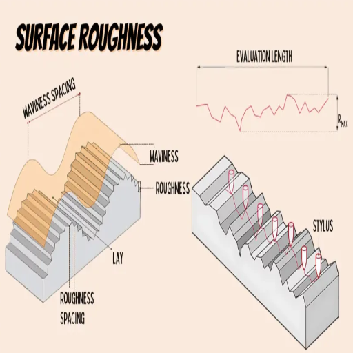
As with anything, surface roughness has precision instruments such as profilometers to gauge values with unmatched accuracy. These tools operate by tracing the area and taking recordings with a stylus device to help compute the roughness parameters, such as Ra, which stands for average roughness, or Rz, defined as the mean peak-to-valley height. Noncontact approaches like optical interferometry and laser scanners work perfectly for outstanding accuracy. Such methods are implemented based on the material, type of surface, and the precision needed. These measures are micrometer-based, and for these machines to work, specific standards must be met for effectiveness in production processes.
Contact Profilometers
Principle: A stylus executes movements over the surface of an area and records the elevation changes within that area.
Key Parameters:
Ra(Average Roughness): This represents an average deviation/ elevation a surface can incur from the mean value, often measured in micrometers.
Rz: Mean Peak-to-Valley Height: It calculates the mean height between the highest and the lowest over a range of sampling lengths.
Advantages: Extremely accurate, this is best for all material kinds and even surfaces.
Disadvantages: Wyeth causes trivial surface tearing, which is unsuitable for sensitive or soft materials.
Non – Contact Optical Methods
Laser Scanning:
Principle: Conducted by a laser beam supplanting on a surface where light reflected will be dissected for variation intensity.
Key Parameters: Surface (base) texture characteristics in three-dimensional design format.
Benefits: Measures intricate geometries in a fast and non-invasive manner.
Optical Interferometry
Principle: Studies the interference patterns of light reflected off the surface of a material to determine its roughness.
Key Parameters:
It can be measured in the nanometer (nm) range for ultra-precise applications.
Advantages: Suitable for delicate and highly reflective materials which are difficult to measure.
Atomic Force Microscopy (AFM)
Principle: Scans the surface topography using a nanoscale probe to obtain the atomic level resolution.
Key Parameters:
It can measure wonderful textures down to parts of a nanometer (nm) level.
Advantages: Ideal for ultra-smooth surfaces and nanostructured surfaces
Selection Criteria
Material Type: Harder surfaces are more forgiving to contact methods, while delicate materials require non-contact methods.
Precision Needs: General quality assurance requires Rz or Ra values, while measurement in the nanometer scale requires optical interferometry or AFM.
Speed and Accessibility: Provides quick results but may lack precision found in AFM.
These techniques and their parameters can provide accurate and dependable surface roughness measurements for different applications in multiple industries.
To comprehend roughness terms like Ra, picture them as the mean of the deviations from the surface profile to the line of best fit of the surface profile (in micrometers). Ra is the most common since it assigns a single number to roughness. However, one must note that Ra is just an average that ignores the details of peaks, valleys, and other irregularities.
Some other correlating technical parameters are:
Rz is the average of the most prominent five peak-to-valley distances. Roughness extremes on the surface can be more directly assessed.
Rq (Root Mean Square Roughness) is a statistical approximation of roughness where emphasis is placed on more considerable deviations since the values are squared.
It refers to the total height of the roughness profile. It is the distance between the profile’s highest peak and lowest valley.
Each parameter serves a specific function depending on the application’s accuracy needs. For instance, Ra is suitable for general comparisons, but Rz and Rt are more useful for functional evaluations where the surface extremes are essential. Multiple parameters can be used to accomplish more complete surface texture characterization.
These surface finish charts help provide control and consistency to my measurements. When employing them, I always check the measured surface texture parameters, such as Ra, Rz, and Rt, against the values provided in the chart. For most general cases, the average roughness, which is roughness, is my primary option. When surface peaks and valleys impact performance, Rz, which is the mean height of the surface irregularities, is beneficial. When significant differences exist in the surface’s texturing, the profile’s total height, Rt, becomes essential. With these parameters, I can ensure that the surface finish will meet the design and functional requirements, guaranteeing that the objectives will be met.
Surface finishing symbols denote features and alterations on the surface of parts or components, which must be completed to ensure the surface texture fulfills its intended purpose. These symbols detail such features as roughness, lay, and waviness that are critical in accomplishing the intended functionality and beauty of the finished product. Types often used include the basic symbol (a check card figure) to show required machining, the material removal allowance symbol, which shows the area of allowed material removal, and symbols with more notations indicating roughness values, directionality, and finishing processes that are specifically called unique. Utilization of the symbols eases the interaction between designers, manufacturers, and engineers, aiding them in working efficiently to meet the specifications of the design provided.
Surface finishing is fundamental to components’ functioning and aesthetic appeal, and embodying specialized techniques is just as crucial. Here, we provide insight into a selection of these methods and their particular strategies: Compared to other processes, surface finishing offers unsurpassed benefits, including high precision of geometric dimensions and the attainment of a superior smoothness of the surface.
Grinding:
Goal: To attain high-dimensional accuracy while achieving superb surface finish as well.
Technical Parameters:
Surface Roughness (Ra): “10” and “16”
MRR: Moderate
Common abrasive: Aluminum oxide, silicon carbide
Polishing
Goal: Surface smoothness and aesthetic appeal are accentuated by polishing away any visible surface imperfections.
Technical Parameters:
Surface Roughness (Ra): “2.5” or less
Speed of polishing wheel: 1000-3000RPM (Varies with material)
Use of a polishing compound
Sandblasting
Goal: Cleaning, smoothing, or roughening the surface using high-velocity abrasive particles.
Technical parameters:
Abrasive Material Grain Size: 50 – 120 grit
Air Pressure: 40–120 PSI
Surface Alteration Depth: less than or equal to 50 micrometers
Anodizing
Goal: For metals like aluminum, enhanced corrosion resistance and decorative purpose.
Voltage Used: 10 -70 or higher, depending on the alloy and coating thickness
Coating thickness: 5-25 micrometers for aesthetic, 25 – 150 micrometers for hard anodizing
Electrolyte type: Sulfuric acid or chrome acid
Electroplating
Goal: Improving corrosion resistance and electro-conductivity through deposition on the surface of a metal layer.
Provided here are the Technical details:
Coating Thickness – 1-100 mµ.
Current Density – 0.5-5 A/dm².
Material Examples – Nickel, Cr, Zn.
Brushing
Objective – To generate a traditional directional pattern for functional and decorative purposes.
Here are the Technical Instructions:
Grit of abrasive bands or brushes – 60-320 CFC.
Feed speed of component – 10-30m/min.
Any method can be adopted depending on the functional and aesthetic needs and the material to be worked on. These aspects facilitate meeting desired surface standards while optimizing production.
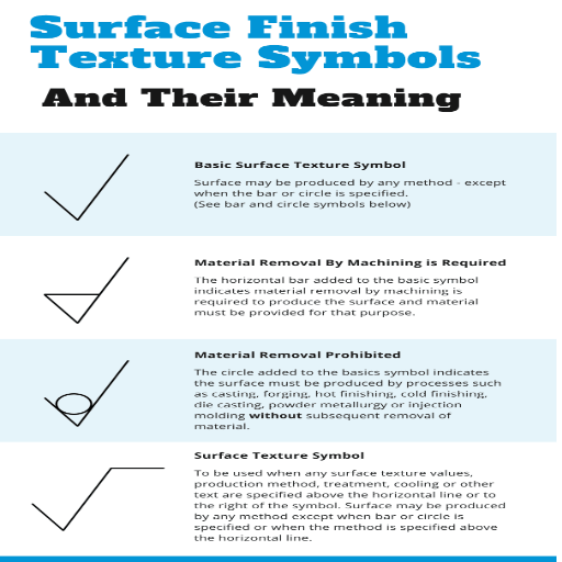
Internationally accepted symbols define surface texture and roughness, adding clarity to technical drawings and facilitating processing. These symbols contain information such as surface finish requirements, machining operations, and relevant roughness values, vital for unambiguous collaboration among engineers, designers, and manufacturers. Such symbols are incorporated in standards ISO 1302 and ASME Y14.36M, among others.
Basic Surface Texture Symbol
This symbol (like a checkmark) specifies a requirement for surface texture without stipulating how it is to be manufactured.
Example Usage: Indicating a surface finish for functional components that requires control.
Machining Required Symbol
The basic symbol adorned with an extra dash signals that machining procedures (grinding and/or milling) must be undertaken to achieve the desired finish.
Example Parameter: Surface roughness is usually in the 0.8–6.3 µm Ra range for machined surfaces.
Non-Machined Surface Symbol
The basic symbol is accompanied by a circle, which refers to surfaces that must not be machined and should retain the material’s original texture.
Example Parameter: The roughness values generally depend on the material and the forming process but are typically >6.3 µm Ra.
Surface Roughness Values
To define exact prerequisites that guarantee proper functioning and/or appearance, specific numbers or ranges (e.g., Ra 0.4–0.8 µm) are given.
Other parameters embrace:
Rz (Mean Roughness Depth) parameters such as Rz 1.0–6.0 µm for delicate finishes.
Rt (Total Roughness Height) is relevant for high-end components.
Using these icons and underlying measurements simplifies interdisciplinary relations and lowers the chances of mistakes, ensuring optimized fabrication by the primary decisions concerning the design.
Considering the standard surface finish requirements in drawings, we concentrate on specific technical parameters essential for meeting the functional and aesthetic needs of the part. Usually, parameters like Ra (Roughness Average) with a value range of Ra 0.4 – 1.6 µm are frequently used for precision or decorative features depending on the purpose. Rz (Mean Roughness Depth) is selected for components needing controlled average surface flatness and is commonly in the 1.0 – 6.0 µm range. Moreover, total roughness height is sometimes defined for parts with special requirements, for which the overall profile height needs to be specified. The parameters are understood as a form of ‘Global English’ of the designers and manufacturers, which help ensure that the product is created to perform as intended and looks like what the design was optimized for, all this in a straightforward, effective manner.

Surface finalization is determined within the manufacturing process. The methods and tools employed in manufacturing directly affect the surface texture and quality. Milling, turning, and grinding processes typically yield finer finishes, while casting or forging operations result in rough surface finishes because these methods have more dominant characteristics. Other factors affecting how a component is finished include tool condition, machining speed, material properties, and the cooling system in place. These variable changes are required to achieve the desired finishing considering functional and aesthetic parameters.
A descriptive and structured breakdown of all the factors that influence surface quality will further help us comprehend the effects of machining processes and their approximate key technical parameters.
Machining Techniques
Turning and Milling: These methods produce smooth finishes with surface roughness ranging between Ra 0.4 µm and Ra 3.2 µm, depending on the feed rate and spindle speed.
Grinding: Grinding can produce ultra-fine finishes, achieving surface roughness values of about Ra 0.1 µm to Ra 0.8 µm.
Forging and Casting: These tend to produce rougher textures with Ra roughness values greater than Ra 6.3 micrometers because no accurate material removal is done.
Tool Condition and Machine Geometry
A better-maintained tool with desirable cutting angles enhances surface quality. For instance, sharp tools’ edges experience less wear, ensuring greater surface roughness.
Cutting tools of high-speed steel (HSS) or coated carbides offer enhanced precision and durability.
Material Characteristics
Softer metals, such as aluminum, are known to produce finer finishes, while rougher surfaces may be exhibited through hard materials, such as steel until advanced cutting tools are utilized.
Cutting variables
Feed Rate: Lower feed rates, such as 0.1 mm/rev for turning, yielding smooth surfaces. However, a rate that is too low will produce an error.
CNC machining achieves desired surface finishes by optimizing many factors, such as cutting tools, material attributes, and machining methods. There are specific tools that, when used, can achieve the desired result with greater ease:
Selection and Quality of the Tool
The quality of the surface finish depends on the selection and care of the cutting tools. For example, using sharper tools minimizes deformation and roughness.
Tools of advanced materials such as carbide, ceramic-coated inserts, and polycrystalline diamond (PCD) offer superior finishes. These materials not only improve tool life but also precision during machining.
Machining Methods
Feed Rate: A lower feed rate to turn is often preferable, with the ideal being between 0.05mm/rev and 0.2mm/rev. Lower feed rates produce finer finishes. However, a feed rate that is too low can sometimes cause tool chatter.
Cutting Speed: Increased speed benefits surface smoothness by reducing material tearing. Softer aluminum materials, for example, can be used at 500-1000 m/min, while more rigid materials are more sensitive to the cutting tool and conditions and require 50-200 m/min.
Depth of Cut: According to balance theory, a cut that is less than 0.1-0.5mm lessens stress on the tool while providing a better finish.
Coolant and Lubrication
Selecting the proper coolant or lubricant lowers operating temperatures, friction, and tool degradation, improving smoothness. Flood coolants, for instance, are commonly used in high-speed operations to control temperature effectively.
Material Considerations
The attributes of the material directly impact the surface finish achievable. Softer metals such as aluminum and brass tend to have dented surfaces that are less smooth, while harder metals need to be carefully modified to avoid being overly rough.
Machine Precision
The inclusion of modern control systems on CNC machines leads to improvement in surface finish consistency. Direct drive motors, linear scales, and thermo-stabilized structures provide repeatable and accurate machining and help in proper tooling.
Observing these parameters allows for efficient and dependable CNC machining, which guarantees the surface finish requirements, hence meeting the desired quality and functionality of the product.
A manufactured product’s surface finish relies on the material’s properties, the cutting conditions, and the machine’s state. Based on my experience, a smoother finish is generally easier to obtain with softer, more pliable materials such as aluminum. In contrast, more rigid materials like steel or titanium require stricter moderation of machining processes to lower roughness. Some primary cutting parameters are feed rate, cutting velocity, and depth of cut. For instance, finer finishes are usually observed with decreased feed rates (0.05 –0.1 mm/rev) and increased cutting speeds (200 – 400 m/min). Also, the cutting tools’ condition, which includes the tool shape and sharpness, is critical; an increase in tool wear leads to an increase in roughness. The machine is also subject to property instability, vibration, or coolant pour, which has a significant influence. Fine-tuning these parameters guarantees optimal results depending on the specific goals for particular manufacturing requirements.

Surface finish remains one of the most critical aspects in engineering design as it affects the component’s functionality, performance, and durability. More excellent surface smoothness can also reduce friction and wear and improve efficiency in moving parts. In addition, surface smoothness increases fatigue resistance due to reduced stress concentrations caused by irregularities on the surface. In some applications like sealing, precision in surface finish is critical as an improper finish can lead to unsealed gaps. Also, it affects the aesthetic appeal by promoting corrosion resistance due to reduced environmental damage and improves reliability by ensuring uniformity. Undoubtedly, achieving the required surface finish increases the reliability of engineered products.
Surface finish symbols are part of the dimensions on technical drawings, indicating the details to be followed to achieve a given surface finish. These symbols also outline details related to surface roughness, including essential surface parameters and measuring waviness, roughness, and lay. They ensure these parameters are achieved during production, and the intended quality is manufactured.
The main technical parameters of surface texture symbols include:
Roughness Average (Ra): The average value of examined surface profile deviations from the mean line is usually defined and indicated in micrometers (µm). Typical values vary from 0.1 µm for highly polished surfaces to 25 µm for rougher surfaces.
Maximum Roughness Depth (Rz): The average height of the maximum peaks and deepest valleys from a baseline within a defined sample length.
Lay Symbol: Defines the direction of a surface texture, which may be circular, parallel, or cross-hatched as per the requirement.
Waviness (W): The combination of surface variations that is broader in scope and spaced further apart compared to the roughness that often affects the orientation and functioning of the part.
Cutoff Length: The cut length is used to roughen the surface depending on the accuracy required by the application.
Surface texture symbols corresponding to these parameters help the designer and manufacturer communicate design ideas and specifications more easily. This enables them to meet the engineered components’ desired functional, reliability, and appearance objectives.
Several factors need to be carefully analyzed and managed to maintain surface quality and functionality. Surface texture affects components’ performance, lifetime, and system integration in an engineering system. Here are the most essential determinations concerning the specific technical parameters:
Material Choice: The selected material profoundly determines the expected surface finishes. Certain metals, such as stainless steel, are easier to machine and give finer roughness values (lower than Ra 0.4 um for mirroring) than more complex materials, resulting in coarser but more durable surfaces.
Production Methods: Different techniques bring about different surface finishes:
Grinding and Polishing Achieves excellent finishes with Ra between 0.02 um and 0.4 um.
Milling or Tuning – Gives a medium rough surface from 0.4 to 3.2 um Ra.
Casting or Sandblasting gives rough surfaces with a finish Ra above 6.3 um.
Specialized Subsurface Traits: Surfaces must be adapted to fulfill their purpose:
Sealing surfaces need ultra-smooth Ra (<0.1 um) to avoid leaking and precisely seal.
Wear-resistant components may have engineered roughness (Ra 1- 4 um), which helps with lubrication retention.
For the best clarity and light transmission, optical components should have excellent Optical smoothness, often worse than Ra 0.01 um.
Spectroscopic Processes: Specialized instruments, such as Surface Scanning Keyence and peripheral measuring systems, can exploit contact and non-contact laser time-of-flight distance measurement to create a virtually modified view based on surface texture contaminate measurement systems.
Contact Profilometer Systems: Measure Ra parameter, Methos Rz, and Rq parameters non-contact (Profiler)-(finger-Non).
Control of Standards: Interdependency on international norms or industrial terms such as ISO 4287 ASME B46.1 is imperative for compatibility utilization and quality homogenization. For instance, Ra Average Roughness is the value for the double-mean vertical offset area of the rough-up surface, and the rough-down deviation is from the middle line of the surface to be machined. RZ focuses on horizontal maximum roughs as a depth parameter, and RP is the height of peaks reached at the deepest point, zero of all peaks.
Meticulously careful inspection of construction material combined with the skillful and precise application of advanced technology could, together with self-supporting claimed quality, fulfill custom and preset surface requirements for any of the technical constraints.
In determining the correct surface profile for an engineering task, I always consider the application’s specific requirements and the component’s functionality. For example, a high Ra (Average Roughness) value might be justified in applications that require strong adhesion, such as coatings and adhesives. In contrast, a low Ra value is essential for smooth, wear-resistant finishes in precision parts. This is similar to Rz (Maximum Roughness Depth), which considers the range of peak-to-valley changes and is essential for other functions such as sealing or lubricating. More details can be provided using parameters such as Rsk (Skewness) and Rku (Kurtosis), which aid in determining surface-bearing capacity and surface population.
I ensure that the selection is accomplished within the limitations of standards, such as ISO 4287 or ASME B46.1, while also considering the set environmental conditions, the technological capabilities of the manufacturing processes, and the economic limits. In doing this, the surface profile is specified from the surface functional dimensions regarding technical parameters, such as Ra for medium texture or Rmax for peak values. Thus, the surface profile enables optimum performance and reliability in various engineering applications.
Leading CNC Metal Machining Provider in China
A: Surface finish symbols are graphical representations used in technical drawings to convey a mechanical part’s desired surface texture and quality. They provide information about the surface roughness, lay, and any additional processing required for the surface. Understanding surface finish symbols is crucial for achieving the correct surface geometry and ensuring the part functions as intended.
A: To dive into surface finish concepts, one should learn basic terms such as surface roughness, lay, and texture. A guide to surface finish symbols and their meanings can provide a comprehensive understanding of how they are used in engineering drawings to represent surface characteristics.
A: Average roughness, often denoted as Ra, is a surface finish parameter that measures the average surface height deviation from the mean line over a specified length. It is widely used in engineering to quantify the roughness of a surface and is a critical factor in determining the part’s performance and aesthetic.
A: A guide to surface finish symbols typically explains the various symbols used to represent surface texture, their meanings, and how they relate to specific surface finish requirements. These symbols are graphical and standardized to ensure consistent communication across engineering disciplines.
A: Understanding surface finish is important because it affects mechanical components’ performance, durability, and appearance. The surface finish can influence friction, wear resistance, and the ability to form a proper seal. Correctly interpreting surface finish symbols ensures that the manufactured parts meet the specifications and function as intended.
A: Surface roughness symbols are specific graphical representations used to indicate the roughness of a surface on technical drawings. These symbols help engineers and manufacturers understand the level of surface irregularities and the type of surface finish required to achieve the desired surface texture.
A: Surface finish symbols represent surface characteristics using standardized graphical symbols that indicate the desired surface roughness, lay, and additional surface processing. These symbols are essential in technical drawings for mechanical parts and provide crucial information for manufacturing and quality control.
A: Surface lay refers to the direction of the predominant surface pattern, usually resulting from the manufacturing process. It is an essential aspect of surface finish because it can affect a part’s function, particularly in applications where the surface interacts with other components. Surface finish symbols often include details about the required surface lay to ensure optimal performance.
A: Measurement methods for surface finish, such as profilometers or optical devices, help assess the surface height, roughness, and texture of a component. These measurements are critical for quality control as they ensure that the part meets the specified surface finish parameters, reducing the risk of functional issues or failures in the finished product.

Manufacturing processes are quite complex, and the choice of a production method is directly related
Learn More →
There are two major manufacturing methods for producing plastic prototypes that most people find useful
Learn More →
As a person involved or interested in the design and production of plastic components, it
Learn More →