

Manufacturing processes are quite complex, and the choice of a production method is directly related
Learn More →
In the field of sealing mechanisms, one of the most ubiquitous components used from automotive to aerospace industries are O-rings. Effective performance of O-rings largely depends on the accurate design of O-ring grooves which, unfortunately, is often neglected. This guide is designed to give you a detailed comprehension of seal O-ring groove design including pertinent parameters, practical tips, and challenges that need to be dealt with. Regardless of your experience as an engineer professional or your novice status, this guide will help you understand the complexities involved in O-ring groove engineering with the ultimate aim of optimal sealing performance.
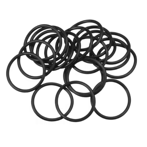
An O-ring requires the proper compression and prevents extrusion damages, a necessity for the accurate O-ring groove width, depth and diameter.
To effectively seal an O-ring, the percentage of cross-sectional compression, or the compression ratio, requires the utmost precision. This acts upon abrasive forces while eliminating premature wear or failure within an O-ring seal.
Leaking as well as durability factors for both sealing and groove surfaces is enhanced from accommodating surface finishes over the recommended Ra values.
Operating conditions are ideal for the application of the O-ring with the combination of optimal clearance between mating surfaces and the lack of looseness within tolerances.
Chemical exposure, temperature and pressure from the operating environment requires blend-free O-ring and groove materials to prevent degradation which render them unusable or crushed.
Seal integrity overtime is maintained with variation allowances in temperature due to material expansion for thermal consideration.
High pressure applications utilize backup rings to offer support for the O-ring while preventing extrusions during extreme condition exposure.
There are specific parameters and dimensions to be observed as precise to prevent malfunction and assure the ideal performance is met from the groove design. The following lists answer specifications and values for reference.
Expansion and compression of the O-Ring require the groove width to accommodate and be larger than the O-ring cross-section.
General guidelines suggest that the width should be equal to 1.1-1.5 times the cross sectional diameter of the O-Ring (CS).
D: The depth of the groove determines how much squeeze is given to the O-ring. For general static applications, the squeeze should roughly be between 20%-30%. For dynamic applications, a 10%-20% squeeze is preferred. The depth can be calculated using the formula:
D = CS – (Percent Squeeze/100 x CS)
Surface Finish: The roughness of the groove directly affects the seal’s effectiveness. Recommended surface roughness values for static seals are generally Ra 16-32 micro-inches and Ra 8-16 micro-inches for dynamic seals.
Lead-in Chamfer: A chamfer for O-ring assembly should be incorporated into the groove with an angle between 15∘-20∘.
Fill Percentage: To avoid over compressing the O-ring, the groove should not exceed an 85% fill underneath max compression. This allows for the material to expand due to varying pressures afterwards.
Radial Clearance: Proper radial clearance between adjacent parts is crucial to allow easy flow of the O-ring under pressure, without the risk of extrusion. This is determined by the material durometer and the specific pressure of the application. Clearances of 0.001 inches to 0.005 inches are common.
Complying with these criteria and employing accurate manufacturing processes guarantees that O-ring groove design provides reliable seals that operate effectively within their environment. It is equally important to carry out simulations and tests for validation purposes.
The width of the groove must be sufficient to house the O-ring, while also allowing for the possibility of thermal expansion or swollenness of the material.
Average groove widths are constructed to be 1.25 to 1.5 times the width of the O-ring sectional circumference.
The depth of the groove must enable sufficient compression of the O-ring in order for it to seal properly.
The recommended seal compression for static positioning is 20% to 30% of O-ring diameter cross-section.
Having a certain degree of clearance facilitates the O-ring not being extruded or pinched at operational compressions.
The desired clearance ranges from 0.001 inches to 0.005 inches, depending on the output pressure and hardness of the O-ring.
The measured hardness of the O-ring material in Shore A influences the optimal groove dimensions and the amount of compression that needs to be applied.
Soft materials may not need as much compression to increase elasticity and avoid compromising the material.
To prevent extrusion, less clearance and high precision tolerances are a must for systems utilizing high pressure.
For pressures above 1500 psi, additional design backup rings may be needed.
Operating temperatures impact expansion and contraction of the material, which means groove dimensions need to be adjusted for these changes.
In the design, the expansion coefficients of the O-ring and the housing must be accommodated.
For proper sealing and to minimize the O-ring’s abrasive wear, the groove surface finish needs to be smooth.
Surface roughness maximally should not exceed 32 microinch (0.8 micrometer) Ra.
The gland geometry in the applications determines how effective the seal is therefore plays a very important role. Some important ones include the gland depth, gland width and the squeeze percentage on the O-ring. These points will guide you through the specifics of the gland depth:
Gland Depth:
The Gland depth directly determines how much compression or “squeeze” is applied on the O-ring.
The gland depth is designed in a way that the squeeze achieved is between 10% and 30%, depending on what the application demands.
Gland Width:
O-ring gland width is critical to achieving proper O-ring accommodation and avoiding urethane extrusion.
Recommended gland width is between 1.5 to 2.0 times the O-ring cross-sectional diameter.
Squeeze Percentage:
The degree of compression, or squeeze, determines the effectiveness of the seal against a possible fluid leak.
For static applications, a typical squeeze is in the range of 15% – 25%
For dynamic applications (such as reciprocating motion), the recommended squeeze is lower, typically 10% – 20% in order to minimize wear.
Tolerances:
Gland dimensions must be toleranced to account for manufacturing variability.
General tolerances in sealing systems are ±0.001 inch (±0.025 mm) for critical dimensions.
During the design phase, all these parameters and their interactions with material properties and operational conditions, are needed to be calculated and tested for sealing effectiveness and reliability over time.

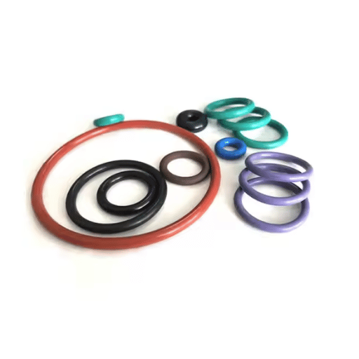
There are many factors to consider including chemical compatibility, temperature, and other application specific requirements when selecting O-rings materials. Due to its flexibility at rather extreme temperatures (-75F to 450F or -59C to 232C), silicone is a good candidate in one of the O-ring applications. On the contrary, silkone is not recommended for severely abrasive environments that are exposed to petroleum based fluids.
Other Viton or fluorocarbon compounds perform well in chemical resistance due to their structure, oils and fuel, and even high temperatures. Their operating range is often between -15C to 400F or -26C to 204C. EPDM or ethylene propylene diene monomer are used when water and steam or brake fluid application is involved, but petroleum based oil is not compatible with EPDM.
Consideration of environmental exposure, mechanical stresses, and even regulatory constraints like FDA guidelines for food and drugs are quite important. Therefore, these methods have certain benefits and drawbacks and using them require validation of scope, testing material performance under certain operational conditions and ensuring reliability are necessary.
Durometer, which measures the softness or hardness of a material, is critical in its selection because it substantially impacts how the material will function in a specific application. A highly rated durometer material is harder, has resistance to deformation, and is thus suitable for applications requiring structural support. Softer, lower durometer materials on the other hand, are more flexible and have better sealing capabilities. The selection of material with the right durometer value is dependent on the operational requirements, including load, pressure, and environmental factors, to achieve functionality and longevity of the material.
The table below offers a detailed comparison between Viton and other commonly used O-ring compounds, including their distinguishing features and performance traits:
EPDM (Ethylene Propylene Diene Monomer):
Temperature Resistance: Performs well in extreme temperatures ranging from -55 – 150 degrees celsius.
Chemical Resistance: Strong resistance to water, steam and polar solvents. Also resistant to ozone, aging and weathering.
Strengths: Best fit for outdoor and steam applications along with systems that require ozone resistance.
Weaknesses: Unfit for oil and gasoline use, along with hydrocarbons.
Neoprene (CR):
Temperature Resistance: Performs well in extreme temperatures ranging from -40 – 110 degrees celcius.
Chemical Resistance: Moderately resistant to oils and chemicals, while also showing good resistance to weathering and ozone.
Strength: Highly resilient to wear and tear making it suitable for use in several industries.
Limitation: Limited high-temperature capabilities, along with lower chemical resistance than specialized compounds.
Polyurethane (AU/EU):
Temperature Resistance: Performs well in extreme temperatures ranging from -54 – 100 degrees celsius.
Chemical Resistance: Excellent for resisting abrasion, cuts, and tears, moderate for oils and other solvents.
Strengths: Well suited for applications with significant mechanical strength requirements, working under heavy loads and high pressure.
Limitations: Lacks low-temperature flexibility, and is prone to hydrolytic degradation in water.
Such information allows engineers and other relevant users to choose an optimal material depending on operational and environmental conditions, thereby guaranteeing effective and enduring sealing systems.
Attaining a reliable seal while avoiding premature failure rests upon achieving an O-ring groove design form that meets the pertinent criteria. Below are some suggestions:
Exact Stroke Values: Follow the prescribed tolerances in the groove values with respect to compression, stretch, and application O-ring pressures. In static applications, typical compression ranges between 20-30%, while in dynamic applications it is at 10-25%.
Finish, Surface and Relief: Aiding seal performance and wear reduction call for smooth surfaces with Ra 0.4-1.6 um. High pressure relief clearance for movement in dynamic designs should be made available without restriction, while prevention of extrusion in static designs should be catered for.
Compatibility of Materials: The working conditions such as temperature, chemical agent, and lubricant dictate the type of O-Ring material to be chosen. A use case is fluoroelastomer (Viton®) which works well in high temperature and chemical sensitive environments.
Considerations for Pressure and Thermal: Inadequately stressing the seal will occur if the O ring and housing materials thermal expansion, pressure changes, and relief cuts are not considered. In cases where material extrusion is highly probable, backup rings may become necessary.
Utilization of Standards: Design standards such as the AS568 dimensions must be checked for compliance and accuracy. During the design stage, simulation tools and software should be employed for best performance analysis.
When these design principles are rigorously adhered to, engineers will be able to increase the seal life, decrease maintenance, and improve the reliability of the system using O-ring technology.
To prevent extrusion, ensure the proper material and hardness of the O-ring corresponds to the application pressure. In cases of O-ring deformation where there is high pressure or high clearance, backup rings should be used. In addition, reduce clearance gaps by following tolerances and properly designed grooves and gap widths should be ensured.
For other common issues, perhaps due to poor installation or because of chemical incompatibility, always check material compatibility with system fluids in addition to following installation directions to mitigate damage. Regular inspections also help to identify wear and degradation before failure occurs.
In the case of O-rings, compression is one of the most important factors concerning the rings’ operation and lifetime. Too much compression leads to over-deformation – loss of elasticity and eventual seal failure – whereas too little compression results in gaps where fluids can escape the seal mechanism. Research suggests that for most O-rings the best compression is achieved with 20% to 30% compression, depending on the material and application. For instance, silicone O-rings are softer and therefore best at 25% compression, but fluorocarbon (FKM) O-rings seal best at closer to 20%, which is still compressive but does not deform the material too much.
The data also show the effects of compression set resistance of the seal on complete confidentiality. A material with high set values is at risk of permanently being deformed and therefore incapable of maintaining a seal during cyclic pressure. For example, in a 70 hour test at 100 degrees celsius Nitrile rubber (NBR) had a compression set of about 18% while polyurethane had approximately 8%, illustrating better recovery.
Correct sealing compression has to accompany groove design so that the O-ring cross-section is uniformly compressed over its surface. Considering the right material conditions and other external factors, maintaining the correct compression parameters allows for greater seal integrity, even with more rigorous applications.
Calculating the appropriate O-ring groove dimensions factors sealing efficiency and durability and requires a careful calculation approach. The processes are made easier through the use of an O-ring calculator available online that considers gland depth, groove width, and O-ring stretch. Users must provide the O-ring material type, cross-sectional diameter, and expected working conditions such as pressure, temperature, and media to obtain relevant results.
Most calculators incorporate industry standards, AS568 or ISO 3601, which ensure the calculations provided are accurate. They help prevent common mistakes such as extrusion, over-compression, or under-squeeze leading to seal damage in no time. An example would be the recommended squeeze percentage of 20-30% for static seals and 5-15% for dynamic seals as a minimum requirement for effective sealing. With these inputs, the designers could develop groove shapes that precisely meet the operational parameters provided.
Standard AS568B specifies the universally accepted dimensional and tolerances limitations for each O-ring used in sealing context. It specifies the cross-section O-rings’ diameters as well as the inside diameters to ensure wider applicability across different sectors. These provisions enable engineers to specify O-ring diameters and mitigate chances for misfit or seal fail.
In analyzing O-ring grooves, it is crucial to consider the circumferential cross-section, type of movement ( stationary vs. rotatory), and level of squeeze. Static seals should obtain 70%-90% of the O ring cut depth or cross-sectional diameter while dynamic cut depth should be looser, at about 60-80%. In addition, the groove of a dynamic seal should be wide enough to relieve the net extrusion pressure without allowing material deformation. In particular, maximum net deformation envelope should be lesser than the predetermined material envelope limit. Finally, design expansion, material hardness, and pressure limits should be included in the calculations as they will affect the role and duration the seal performs in the scope of its pre-defined operating conditions.
Axial face seals are intended for use with forces acting normal to the sealing face. These features are appropriate in cases where a stationary and a moving parts interface, such as in flanges or lids. Important design features for axial seals are groove depth, groove width, and squeeze percent. For example:
Axial seals also have to deal with other concerns such as the tolerances of misalignment, the environmental conditions like temperature and chemicals for compatibility reasons, and thermal expansion. The design can also be modified by the pressure range with high pressure needing backup rings or materials with special compounds to avoid extrusion.
Data from performance analysis suggest that for axial O-ring seals, the 200-degree Fahrenheit mark invites an increase in compression set, mainly in low thermal resisting materials like nitrile. Better performing compression set materials like fluorocarbon or silicone (<15% compression set over cycles) may perform better under such conditions.
Financial Radial impulsion sealing involves certain difficulties because there is a need to hold the charge at specific value which is equal to the axial load and to ensure constant contact of the seal with moving contour. Seal failure is possible for a combination of factors such as non-uniform wear, dynamic motion, and material compatability with high pressure or aggressive chemical environments. Use of stronger PTFE with fillers or perfluoroelastomers can improve these problem’s seals’ wear resistance and durability. From spring loaded seals when used in dynamic arrangements contact pressure is constant and gland machining can minimize misalignment. Also, extensive testing of materials in simulated service conditions is advised for dependable performance over time.
In radial seals, backup rings have a significant effect in improving seal efficiency, as well as in deepwell applications. These rings are constructed from strong materials, normally PTFE or high strength polymers, and serve the purpose of blocking the primary sealing component from exrtruding into the clearance gap under high pressure conditions. Literature suggests that applications above 5000 psi are greatly improved by the inclusion of backup rings, as the chances of seal extrusion are lowered by 70%. This greatly improves operational lifespan.
For example, backup rings give seal’s dimensional stability and exhibits no signs of extrusion after 500 cycles. In a 1,000 psi to 10,000 psi pressure cycle, seals without backup rings showed deformation after 150 cycles, When compared side by side, these results put forth a compelling case on the need of a backup rings for seal sustainabilty in tough conditions.
A: Considerations include ensuring that the O-Ring material is compatible with the operative environment, understanding the cross sectional requirements, and complying with design limits which avoid extrusion and guarantee adequate O-Ring compression. In addition, proper selection of O-ring and gland dimensions is necessary to achieve effective sealing.
A: Appropriate O-ring size determination entails considering the groove’s outer diameter and checking the Parker O-ring Handbook. There has to be a correspondence with the cross section requirements of the application, and also need for the size selection to be within basic O-ring grooves contouring standard.
A: The difficulties linked with the designing O-ring grooves for O-rings in reciprocating applications include control of dynamic stresses, prevention of wear, and assurance of an adequate seal during the whole motion of the O-ring. These challenges have to be managed with material properties and groove tailoring for the seal to be reliable and durable.
A: Material selection impacts O-ring groove design in the selection of the materials that the O-ring will be subjected to during its application lots of heating or cooling, subjected to chemicals’ attacks, or put into mechanical activities as well. Selecting the right material will always provide the O-Ring with the long life and sealing ability even in the harsh circumstances.
A: Standard O-ring grooves are created using established dimensional guidelines meant for basic, commonly used applications while custom designs are developed to fit particular needs that standard grooves cannot fulfill. Custom O-ring grooves are often required in specialized design applications where standard solutions have been proved ineffective in providing required sealing capabilities.
A: Knowing the cross-section of an O-ring is essential because of its impact on the sealing’s effectiveness and the necessary force needed to achieve it. It dictates how the O-ring will be compressed and how much it will adapt to the groove, and therefore, it must be integrated with the design parameters to achieve effective results.
A: For O-ring design, dimensioning, and material recommendations, technicians may consult the Parker’s O-ring Handbook and Trelleborg and Global O-ring and Seal’s supplier guidelines. These documents include broad details of gland design and dimensioning criteria, which is helpful for sketching seals with O-rings.
A: Types of standard grooves for O-rings comprise static and dynamic grooves, which further divides into reciprocating and rotary designs. Every type has specific functional movement and force applied on the O-ring to maintain a seal under different conditions.
A: A Custom O-ring that comes with O-Ring grooves have a specific design called a dovetail groove, this design angles in order to cut and securely fasten the O-ring. This Design is used where the chances of losing the O-ring due to pressure changes are high.
A: As for others, it all begins with the supplier’s knowledge about O-ring grooves; the materials they have; the different sizes they provide; and whether customization is an option. It’s the case with Trelleborg and Global O-Ring and Seal who also provide product and technical support to their customers. Suppliers go to for O-ring components and relations of this nature.

Manufacturing processes are quite complex, and the choice of a production method is directly related
Learn More →
There are two major manufacturing methods for producing plastic prototypes that most people find useful
Learn More →
As a person involved or interested in the design and production of plastic components, it
Learn More →