

Manufacturing processes are quite complex, and the choice of a production method is directly related
Learn More →
Surface roughness is essential in assessing the quality and functionality of manufactured parts, as it affects performance, endurance, and interoperability. The Ra, which stands for Roughness Average, is arguably one of the most prevalent standards for measuring surface clarity. This post comprehensively outlines surface roughness measurements, focusing on the Ra standard, its computations, interpretations, and usefulness.
We will examine surface roughness relevance across different fields, define relevant vocabulary, and outline the tools and techniques incorporated to attain accurate measurements. Likewise, the article will explain how these measurements affect engineering judgment and product quality. If you fall into one of these categories: industry expert, engineering undergraduate, or someone interested in this critical component of manufacturing, this article will assist you in gaining the most pertinent facts on surface roughness measurement and its importance in today’s world.

Surface irregularity describes the texture of a specific surface defined by its tiny inconsistencies and deviations from a hypothetic flat surface. The heights, depths, and spacing of these markings customarily gauges it. Roughness assessment is crucial because it influences mechanical systems’ friction, wear, and oiling efficiency. It also affects product use, aesthetics, and functionality in various industrial sectors, including aerospace and medical, thus crucial in precision engineering and manufacturing.
Complex geometric structures where surfaces are inclined and blended toward a blend line require classification of great importance. Roughness is quantitatively expressed by specific technical parameters that allow fast surface texture characterization. The most important parameters are:
Ra (Average Roughness): The arithmetical mean of absolute values of the surface deviations. Widely used parameter that provides a general measure of surface texture.
Rz (Mean Roughness Depth): The value of the mean level of roughness accepted in measurement units.
Rt (Total Roughness): The measured distance from the highest peak to the deepest valley throughout the length of the measurement.
Rq (Root Mean Square Roughness): The standard deviation of the mean level of squares of the surface deviations.
Depending on the accuracy needed for a particular application, these measurements are often done in micrometers (µm) or nanometers (nm). The proper parameter is chosen by combining the product’s features, production methods, and specific quality assurance requirements.
Surface texture is a crucial parameter that significantly affects a product’s efficiency, durability, and effectiveness. The surface of a product plays a vital role in its interaction with the environment, affecting friction, wear, adhesion, and reflectivity, for instance, with mechanical parts. These smoother textures have low Ra values, like 0.4 µm and 0.8 µm for precision parts, lower friction, and wear. Alternatively, increasing surface roughness, such as 1.6 micrometers to 3.2 micrometers, can increase adhesion for coatings and bonding.
The principal surface texture assessment indicators are Ra (Arithmetic Mean Roughness) used for general surface quality, Rz (Average Maximum Height) marking the peak-to-valley difference, and Rq (Root Mean Square Roughness) representing the entire roughness torn apart statistically weighted roughness derived from larger discrepancies. International regulations like ISO 4287 and ASME B46.1 control how accurately these parameters are measured and assessed across different scopes of use. Specifying the correct texture in the aerospace, automotive, and medical devices industries usually determines product effectiveness while satisfying high-quality requisites.
Surface roughness directly impacts component performance related to wear resistance, friction, and seal creation. For example, in high-precision jobs, smoother surfaces are less prone to friction and are more efficient, while controlled roughness may aid in improving grip or bonding adhesiveness. Significant technological parameters include arithmetic mean roughness (Ra) – which measures average surface deviation – as well as root mean square roughness (Rq), which evaluates the peaks and valleys statistically, and peak-to-valley roughness height (Rz), which assesses the maximum vertical distance. These parameters are essential for optimizing manufacturing processes and providing reliability in harsh conditions in high-tech disciplines such as aerospace or medical equipment. The standards provided will ensure both the usability and durability of the product.
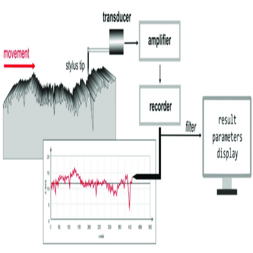
The instruments for measuring surface roughness include tactile and optical devices for texture evaluation. Tactile methods, like stylus profilometers, incorporate mechanisms that trace the surface to capture height differences. At the same time, interferometry or laser scanning are optical methods that analyze patterns by reflecting light off the surface. These devices produce accurate values depicted in roughness parameters such as Ra, Rq, and Rz that express the value of divergence and irregularities in a given surface. These measurements are vital to a specified standard requirement, to enhance the product’s performance, and to improve the quality of the outcomes.
Surface roughness can be evaluated through various methods that differ in their particular application and the degree of accuracy required. Among the most usual techniques are:
Contact profilometers apply a fine stylus that directly contacts the surface during measurement to capture changes in height. As the stylus moves along the sample, it captures the height of peaks and roguish features and transforms them into electrical signals, which are then used to construct a surface profile. Some of the key parameters that can be computed include Ra (mean roughness), Rq (root mean squared roughness), and Rz (mean height of the roughest surface). These devices are accurate and applicable to small areas, however, their precision comes at a cost of speed when compared to non-contact methods.
This approach does not make physical contact and measures the surface topography through the interference of light waves. Using light reflected from the surface, an interferometer measures the roughness of the surface and produces a 3D representation of it. Interferometers are perfect for measuring fragile materials and very smooth surfaces, and their accuracy values are in the range of nanometers. Surface parameters that are estimated using interferometric techniques include Sa and Sq.
Laser beam scanning systems rapidly detect irregularities in the surface and roughness. These techniques are also relatively quicker, allowing the user to measure high-resolution surfaces accurately. The methods can be used on more complicated geometries or larger surface areas. As with the other technologies, Ra, Rz, and Ssk are also measured, showcasing their versatility in different industries.
AFM is the most refined surface measuring tool because it analyzes ultra-smooth or nano-engineered surfaces. The probe contacts the surface, measuring variations due to its relative displacement. AFM can Measure topography with extreme resolution, facilitating the key roughness parameters, Ra and Rmax.
These methods cater to specific surface textures, materials, and precision levels, providing a solid way to measure surface roughness. The process is selected based on the needed accuracy, sample dimensions, and industry requirements.
Profilometers with a stylus tip
Technical Parameters:
Resolution: Qualitatively lower than 10 nanometers.
Measurement Range: Conventional 1 mm – 50 mm.
Applications: Most appropriate for 2D surface profiles and Ra, Rz, and Rq parameters.
Additional benefits include their high accuracy and direct measurement of surface changes, which make them applicable to a broad spectrum of industries.
Optical Profilometers
Technical Parameters:
Resolution: 10 microns to 100 microns. Sub-micron accuracy.
Measurement Range: Vertical range of a few millimeters without contact.
Applications: More familiar in the electronics and ultra-precision mechanical fields.
They work using light interference of surface features and are suitable for soft and sensitive materials.
Atomic Force Microscopy (AFM)
Technical Parameters:
Resolution: Up to 0.1 nm. Atomic scale.
Scanning Area: Usual 100 μm x 100 μm.
Applications: Most suitable for surfaces with roughness at the nanoscale and needing elaborate observation, especially in research and semiconductor industries.
It gives precise 3D data and extraordinarily accurate details. They are used when utmost accuracy is needed.
Laser Scanning Confocal Microscopy
Technical Parameters:
Resolution: As good as 10 nm.
Measurement Range: Depth classification of approach up to 2mm.
Applications: Good for complex 3D surfaces and reflecting and transparent materials.
Often used in the construction of medical devices and the study of materials.
These tools ensure accurate and dependable measurements while providing unique capabilities suited to surface analysis. Careful consideration of their technical parameters ensures proper selection for specific materials and textures.
The roughness profile is a fundamental representation of the surface’s profile irregularities measured over a specified contour along the surface. It shows how the peaks and valleys of a surface along the specified contour differ from a reference plane, illustrating the characteristics of the texture. Studying this profile assists in assessing the wear, adhesion, and performance of different materials. Some of the parameters that are commonly related to the roughness profile are:
Ra (Arithmetic Mean Roughness): Average magnitude of surface height deviations from the mean line.
Rz (Maximum Height of Profile): The maximum vertical distance from the tallest peak to the deepest trough within a given span.
Rq (Root Mean Square Roughness) provides a statistical estimation of surface texture by indicating the mean squared values of surface height deviations.
Such parameters are essential for the industry. They involve engineering accuracy and quality assurance so that the materials can serve their functional purposes. The inclusion of roughness profiles in the analysis increases strength and product functionality.

The Ra Value in surface roughness, also known as Arithmetic Average Roughness, signifies the mean of absolute values of deviations from the average height of a designated surface area. It quantifies a surface’s overall smoothness or texture by condensing it into a single numeric value. The Ra value, while simple, easily captures the general roughness. However, describing irregularities or outlier peaks and valleys can be challenging.
Achieved for different industries, the Ra Standard is used as a reference for assessing surface roughness in numerous fields and delineates the acceptable boundaries of Ra values for specific cases to guarantee appropriate function, safety, and performance. The required Ra value can vary significantly depending on the particular use case. For instance,
Material type, operational criteria, and surrounding conditions must be considered when applying the Ra standard. Even though these values provide a supportive measure of roughness, considering other parameters like Rz (Maximum Height of the Profile) or Rq (Root Mean Square Roughness) shall enable further surface characterization for precise tolerances.
The roughness Average (Ra) is calculated as the mean of absolute vertical deviations from the mean line of the surface profile over a given length. This process guarantees the surface roughness is appropriately accounted for. Usually, a mathematical representation is employed, which states:
Ra = (1/L) ∫ |Y(x)| dx,
L is the sampling length, while Y(x) is the vertical deviation from the surface mean line.
Procedure to Determine Ra value:
Gather Surface Profile Measurements: Employs profiling devices to trace the outline of the surfaces accurately.
Establish the Sampling Length (L): Depending on the scope of use, the industry usually acknowledges a standard length that defines the portion of the analyzed surface profile.
Measure Vertical Deviations(Y): Measure deviations from the mean line over the sampling length Marked.
Compute the Values: Calculate the average of absolute values of the measured deviations using a formula value of the Ra.
Significant Technical Indicators:
Profilometer Sensitivity: The Profilometer should be sensitive enough to measure delicate surfaces (Ra < 0.1 µm).
Popular Sample Length (L): This often has values such as 0.8mm, 2.5 mm, or 8 mm, depending on the surface finish and industry parameters.
Distance Units: According to ISO 4287/42888, a cutoff length should eliminate irrelevant signals while capturing relevant surface features.
Following these steps and boundaries, the resulting Ra value is expected to accurately represent the degrees of roughness of the surface for optical, electronic, and industrial purposes with high precision quality standards.
Just like Rz, Ra (The Arithmetic Average Roughness) is more straightforward than other roughness measures, so it is heavily utilized. However, Ra tends to overlook surface profile characteristics. Rz measures the average height difference between the profile’s maximum peak and minimum valley over several sampling lengths, giving him a better grasp of extremes. Rq (The Root Mean Square Roughness) sensitivity to outliers is higher than that of Ra because Rq gives larger deviations with a more significant impact by squaring the height changes. In addition, Rt (The Total Height of the Profile) measures the vertical distance from the deepest valley to the highest peak over the evaluation length, which assists in measuring surface defects.
Main Technical Parameters:
Ra: Arithmetic mean of deviations from the mean line (μm or nm)
Rq: Root mean square of profile deviations (μm or nm)
Rz: Average height of maximum peaks and minimum valleys across several samples (μm or nm)
Rt: Distance between the lowest valley and the highest peak of the evaluation length (μm or nm)
Ra is valid as a base measure, but including Rq, Rz, and Rt improves the analysis for surfaces with distinct textural or quality requirements.
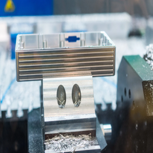
Surface roughness is vital in CNC machining because it influences the finished part’s functioning, performance, and appearance. A surface with precisely controlled roughness enhances surface finish with a better fit, less friction, and additional wear resistance, which is essential for mechanical surfaces. Moreover, surface coatings’ adhesion and corrosion resistance are equally important issues for different scopes of use. Stringent industry standards are easily achieved due to accurate roughness measurements that guarantee quality and reliability in production.
For good surface finish in CNC machining, several factors are, in the first place, controlled and optimized. These are tool selection, cutting parameters, and the surrounding environment. Consider the following key elements with the metrics that accompany them:
Selection of Tool
Always use tools with sharp cutting edges and suitable geometry for machining material.
Use quality carbide or coated tools as they reduce finish wear.
Parameters of Cutting
Reduce the feed rate between 0.05-0.1 mm/rev for smoother finishing.
Use a low Depth of cut (DoC) between 0.1-0.3 mm to reduce tool marks.
Depending on the material, optimize the cutting speed for aluminum at 100-200m/min and titanium at 50-100m/min.
Coolant/Lubrication
Use sufficient coolant to control heat and improve chip removal.
Use high-pressure coolant systems for materials that tend to stick to the tool.
Machine Rigidity and Toolholder
Check that there is no unwanted movement of the machine components during the operation.
Use balanced toolholders to minimize runout during high-speed operations.
Surface Treatments (if required)
Smoothing and strengthening the surface can be achieved by polishing or coating it after machining.
With proper control of the parameters, surfaces with good visual and functional finish quality will be obtained consistently.
The caliber of a machined surface is essential in ascertaining a component’s functionality, performance, and service life. Components with high wear resistance, fatigue strength, and thermal conductivity have a smooth and precise finish. Surface discontinuities may cause failure, increased friction, or poor sealing. Below are short explanations and answers to the topic of surface finish and its relationship with some significant technical parameters:
Modification of Friction and Wear
Energy expenditure in rubbing surfaces is minimized because a finer surface finish reduces friction between interacting surfaces.
Recommended roughness (Ra): 0.2-0.8 µm for high-precision components such as gears or bearings.
Influence on Fatigue Strength
Surface defects facilitate stress concentration, lowering potential fatigue life. Treated or polished surfaces mitigate surface fatigue.
Up to 30% improvement in fatigue resistance is possible due to shot peening or surface treatments like nitriding.
Sealing and Fluid Flow
Highly smooth surfaces enhance the sealing properties of gaskets and hydraulic systems and enable proper fluid circulation in the channels.
Recommended roughness (Ra) for sealing surfaces: 0.05-0.4 µm.
Thermal and Electrical Conductivity
Uniform surfaces are essential because they enhance thermal and electrical performance for heat exchangers or electrical junctions.
Optimizing machining processes and maintaining proper roughness specifications can maximize the effectiveness of a machined surface in meeting operational needs.
For measuring the surface finishes in CNC operations, I depend on the specific tools and procedures available for evaluating the machined part’s roughness, waviness, and general texture. Surface features are evaluated with measuring devices such as contact and non-contact optical profilometers. Essential parameters are roughness, Ra, which is usually of general use, and Rq, root mean square roughness, which is even more advanced considering the surface texture. For general use in CNC, the 0.8-3.2 micron range of Ra is sensible, while for precision machining, it may have to go as high as 0.05-0.4 microns, depending on the relevant factors, whichever the application dictates. Regular calibrating of measuring devices and adherence to ISO 4287 or ASME B46.1 standards guarantee repeatability for both functional and aesthetic requirements.

The methods employed take center stage in the execution of the procedures and determine the surface roughness as different methods produce varying patterns and textures on the surface. For example, machining processes, including turning, milling, and grinding, have various degrees of roughness depending on the tool’s sharpness, cutting speed, feed rate, and material characteristics. Polishing and lapping are abrasive processes that can generate smoother surfaces by reducing the high point’s surface. 3D printing and other forms of Additive Manufacturing have surface roughness traits; as the material is deposited, layers are formed, which can be altered through the surface roughness using secondary processing. The outcome of the surface is also subject to change with the selection of lubricants and coatings and other environmental conditions like temperature and vibration.
Surface roughness in manufacturing is affected by a combination of several crucial factors, each linked to specific technical parameters:
Machining Parameters
Cutting Speed: Higher velocity almost always implies smoother surfaces, except for heat-related deformities.
Feed Rate: Coarser patterns are formed with coarse feed rates, while finer feed rates yield better results.
Tool Sharpness: Sharp tools reduce surface lines while clean cuts are made to the conventional tool, and due to wear and tear, roughness becomes more visible over time.
Depth of Cut: Shallow cuts minimize imperfections on the surface and, as such, are incredibly desirable.
Material Properties
Hardness: The tool wears out with time as the surface becomes rougher due to more complex materials, which is a paradox.
Composition: The machining process may impact the final texture due to the behavior of certain alloys or composites.
Abrasive Processes
Surface roughness improves with finer polishing or lapping grit sizes.
Surface finishing decreases grit levels to achieve uniformity by smoothing the high points.
Additive Manufacturing Characteristics
Layer Height: Smaller layer heights can improve smoothness with reduced stair-step formation.
Post-Processing: Surface quality can be improved with sanding, chemical smoothing, or coating.
Environmental and Operational Conditions
Temperature: Too much heat may change surfaces, leading to deformation or an increase in roughness due to thermal expansion.
Vibration: While machining, uncontrolled vibrations can cause irregularities.
Lubrication: Smooth finishes can be achieved with adequate lubricants that minimize friction.
Surface roughness for any manufacturing process is adjustable and can be improved according to requirements by adequately setting and managing these parameters.
To attain the desired surface finish, it is crucial to make precise settings for the machine and closely follow the technical specifications. Below is a simple summary of tips and best practices as they are most frequently recognized:
Speed and Feed Rates
Cutting Speed: An optimal range should be sustained depending on the material. For metals like aluminum, use speeds from 250 to 400 SFM, and for stainless steel, augment it from 50 to 150 SFM.
Feed Rate: Smoother finishes require slower feed rates, for example, 0.002 to 0.01 IP. Higher feed rates than this number could result in tool marks.
Selected Tools and Maintenance
Material: Frictionless and more excellent tool life would be guarded with TiN (Titanium Nitride) or diamond-like carbon-coated tools.
Sharpness: To ensure sharp cutting tools would mitigate surface tearing that causes roughness.
Geometry: Fine finish tools would have small cutting angles, generally between 5° and 20°.
Machine Stability
Vibration Control: Damping systems or an imbalance of rotating parts must be utilized to lower vibration issues.
Rigidity: Properly clamped and chatter-free parts and fixtures are required to support the machine.
Coolant and Lubrication
A good heat-managing and friction-minimizing working fluid should be used. When used on metals, the flow rate for water-soluble coolants ranges from 10 to 30 L/min.
Ensure proper lubricant application during machining to prevent overheating from excessive concentration.
Depth of Cut
Select the most minor depth of cut during finishing passes—usually 0.002 to 0.01 inches. Better surfaces are obtained when precise passes are taken.
Spindle and Worktable Settings
RPM (Revolutions per minute): Balance the speed and material of the tool and workpiece. Too much speed may worsen the surface quality.
Alignment: The spindle and worktable must be perfectly aligned to avoid uneven cutting or wear of the cutting tool.
With proper adjustments on these parameters and the correct machining methods, manufacturers will consistently produce surfaces of good quality within the required tolerances.
Surface features are essential in production since they impact the final product’s functionality, efficiency, and quality. Proper surface quality can positively impact friction, wear resistance, and the cosmetic appeal of the product. Aspects such as roughness, waviness, and lay require stringent control to comply with industrial standards.
The following are some of the essential details that should be noted:
Surface Roughness(Ra): It should be kept within tolerances of 0.8 – 1.6 micrometers for general application and up to 0.05 micrometers for critical finishing, such as aerospace.
Tool Geometry: Tools with sharp cutting edges should be used to reduce surface log defects.
Feed rate: Should be controlled between 0.004 and 0.012 inches/revolution in case of precision machining. The depth of feed affects the roughness of the surface.
Cutting Speed: Steel should be 75-150 ft/min to ensure tool life and suitable surface quality.
Vibration control: This should be done with some kind of damping or rigid fixturing to ensure operation stability.
Precise values are achievable when controlled, and superior products that meet high-performance demands can be manufactured.
Leading CNC Metal Machining Provider in China
A: Surface roughness refers to the irregularities on the surface of a material. It is quantified by measuring the deviations of an actual surface from its ideal form using parameters such as the Ra value, which is the arithmetic average of the absolute values of the surface profile deviations. Roughness can be measured using tools like profilometers or surface roughness comparators.
A: Ra, or arithmetic average roughness, is a widely used surface roughness parameter. It represents the average roughness value across the surface, providing a general indication of surface smoothness or roughness without detailing individual peaks and valleys.
A: Surface roughness significantly influences the performance and aesthetics of the final machining surface. A rough surface may increase friction, wear, and potential failure, whereas a smoother finish enhances component functionality and appearance.
A: In addition to Ra, other standard surface roughness parameters include Rz (average maximum height of the profile), Rq (root mean square roughness), and Rt (total height of the profile). These parameters help characterize the surface by providing different perspectives on the roughness profile from the mean line.
A: CNC machining achieves a specific level of surface roughness by controlling various machining parameters such as cutting speed, feed rate, tool geometry, and machine tool condition. These factors influence the texture or surface finish, allowing operators to meet desired roughness values.
A: Achieving a 0.4 μm Ra surface finish is significant in industries where high precision and smoothness are critical, such as aerospace and medical device manufacturing. This level of surface finish ensures minimal friction and wear, leading to enhanced performance and longevity of components.
A: Yes, surface roughness can be compared using visual methods such as surface roughness comparators and standardized reference plates with known roughness values. These tools allow for a quick, qualitative assessment of a material’s surface by comparing it to the comparator’s texture.
A: The machine tool is crucial in determining surface roughness, as its precision, stability, and condition directly affect the surface texture parameters. A well-maintained machine tool operating at a constant speed can produce a consistent and desirable surface finish.
A: Surface irregularities can negatively impact the final surface quality by introducing unwanted roughness or surface defects. These irregularities can result from tool wear, vibrations, or improper machining practices, leading to less effective component performance.

Manufacturing processes are quite complex, and the choice of a production method is directly related
Learn More →
There are two major manufacturing methods for producing plastic prototypes that most people find useful
Learn More →
As a person involved or interested in the design and production of plastic components, it
Learn More →