

Manufacturing processes are quite complex, and the choice of a production method is directly related
Learn More →
Holding tight tolerances on PTFE is difficult because the material creeps under stress, expands with temperature changes, and springs back after machining. Standard tolerances for PTFE parts range from ±0.001″ to ±0.005″, but achieving the tighter end of that range requires deliberate strategies around stress relief, fixturing, and tool selection. This guide covers the practical techniques that keep PTFE dimensions within spec across CNC turning, milling, and drilling operations. For full process details beyond tolerancing, refer to our comprehensive PTFE machining guide.

Because of its specific characteristics, PTFE often permits machining tolerances varying between ±0.001 to ±0.005 inches, depending on the size and complexity of the part. Larger components or those with complex geometries may need broader tolerances because PTFE tends to deform under stress. Constant PTFE’s thermal expansion and low rigidity have to be kept in mind when setting tolerances to guarantee dimensional accuracy and overall precision.
The standard machining tolerances of PTFE depend on the following:
By taking all of these notes into account, one can ensure reliability and accuracy for PTFE parts.
These factors illustrate the difficulties associated with machining PTFE and why one needs to adequately prepare or meet all requirements about precise tolerances, good working conditions, and the right PTFE machining tools.
PTFE, or polytetrafluoroethylene, differentially stands out from other thermoplastics, broadly owing to its mechanical characteristics that have a direct bearing on its machinability. For instance, PTFE’s rigidity is much lower than PEEK (polyetheretherketone) or polycarbonate. Additionally, its low rigidity, coupled with a high thermal expansion coefficient, renders PTFE susceptible to dimensional changes in temperature variation or machining operations. This results in far greater looser tolerances as compared to other thermoplastics that are more dimensionally stable.
As expected, PEEK can be machined with dimensional tolerances that are considerably greater than those of PTFE, because of its engineering properties like high tensile strength. In particular, PEEK parts can often be machined with tolerances as tight as ±0.001 inches. Whereas, PTFE-only polyetheretherketone has tolerances in the region of ±0.005 to ±0.010 inches, depending on the specific application and dimensional stability required.
Thermal conductivity is another important factor that distinguishes these materials from one another. The values for specific materials are PTFE: thermal conductivity ~ 0.25 W/m·K, Thermal expansion coefficient ~ 120 x 10-6/°C. PEEK thermal expansion coefficient 47 x 10-6/°C. This tells us that PTFE is more prone to size variations during heating and cooling cycles than PEEK which further intensifies the problems around machining PTFE if tight tolerances are necessary.
Other thermoplastics like polycarbonate and ABS (acrylonitrile butadiene styrene)have tolerances that place them between PTFE and PEEK. Polycarbonate, for example, can achieve tolerances of about ±0.002 to ±0.005 inches under normal machining conditions due to its stiffness and moderate thermal stability. Extruded and injection-molded ABS parts are typically used in lower tolerance applications because their stiffened, swollen, and cold-drawn states are less restrictive than controlling the dimensions of PEEK engineering plastics.
These discussions of comparisons demonstrate the peculiarities involved in machining PTFE and the necessity of properly choosing the most acceptable thermoplastic about the distinct technical, thermal, and mechanical characteristics of the particular application.

The material’s very low coefficient of friction0 which is between 0.05 to 0.10 for solid materials0 greatly affects the machining tolerances. Such a low value of the coefficient of friction leads to a significant reduction in the resistance to mechanical work done during the processes of machining cutting and finishing. It creates problems too, because it tends to make holding the part very difficult due to its extreme softness and slipperiness. This can also lead to undesired changes in the sizes of the parts being machined, resulting in nonconformance to the intended tolerances.
Slower friction also implies that the amount of heat generated by friction is very low, thus reducing the chances of thermal deformation while cutting. This benefit is not unqualified though because of PTFE’s high thermal expansion coefficient which is about 10 steel at 10 x 10^{-5}/K. This leads to the possibility of losing dimensional accuracy when moving in and out of contact with the machining tools. So to achieve close dimensional tolerances it is necessary to control the parameters of the machine tools such as feed rate and cutting speeds as well as temperature conditions. For instance, the use of sharper tools and lower speeds increases the tensile forces and stresses, thus leading to better tolerances being achieved.
Regardless of the complications encountered, sectors such as aerospace and the medical industry that depend on PTFE and its unique characteristics, have made innovations in cryogenic machining or improved fixture designs which allow them to maintain tolerances of ±0.001 inches in critical areas. Such levels of accuracy guarantee that the material is functional while still affording its mechanical and thermal benefits.
Because of creep and PTFE’s unusually low modulus of rigidity, high coefficient of thermic expansion, and self-creep, the material exhibits poor performance when it comes to retaining tight tolerances. PTFE features a measly stiffness of around 4 to 5 MPa at room temperature, which causes the material to undergo dimensional changes even when the supply of load during application or machining is minimal. To add on, the self-expansion of PTFE is around 120 x 10⁻⁶/°C, which is far greater than most metals, which causes dimensional changes when the temperature decreases or increases.
PTFE is prone to deforming under continuous stress, this behavior is termed as creep and special consideration must be paid to it. For example, under static sustained loads at room temperature, PTFE displays a maximum strain of around 1–2% during the first 24 hours of constant pressure being exerted. Due to machining efforts needing to be so meticulous, cryogenically cooled tools and fixtures are at times utilized to cut down on the deformation caused throughout the fabrication process.
Although these difficulties exist, it is still possible for industries to operate within stringent limitations thanks to contemporary strategies, such as CNC machining with specified settings, laser machining, and precision fixturing. Research demonstrates that better than ±0.0005 inch tolerances are feasible with PTFE components for critical aerospace and medical applications, with dependable performance attainable despite the material’s constraints.
The challenge of PTFE machining accuracy hinges on controlling temperature concerning the material’s PTFE high coefficient of thermal expansion (CTE). CTE for PTFE varies in grade and filler composition greatly impacts it, with ranges varying between 100 and 400 x 10⁻⁶/°C. As such, thermal management is required to achieve tight tolerances since PTFE experiences expansion and contraction at that fluctuation. Elevated temperatures can cause the PTFE to deform or swell during precise cuts and assemblies to Teflon, resulting in a loss of accuracy.
To solve these challenges, the machining of PTFE is usually done at controlled ambient temperatures through cooling techniques such as cryogenic machining. Studies show that further precision can be obtained through chilled sub-zero environments, as they reduce thermal expansion while supplying stability for the cutting process. Additionally, thermal cutting processes usually have post-machining stabilization techniques where the finished parts are conditioned at higher than normal levels to relieve stresses accumulated from overuse and ensure dimensional stability.
Temperature-controlled machining environments are required for critical applications for aerospace and medical components that require tolerances to be achieved within +/- 0.0005 inches. These measures ensure that the components retain their integrity and performance over a broad range of operational temperatures often from -328F (-200C) to as high as 500F (260C) which is within the PTFE operating range.

Done with extreme precision, CNC milling tolerances on PTFE can be achieved only with the aid of deliberately planned machining and cutting tool choices, as well as the overall surroundings in the procedure. This is due to the material’s properties. PTFE, which is a non-rigid polymer with high sensitivity to temperature, can be challenging to machine with high precision due to its relatively low melting point of about 327 °C (620 °F) coupled with rapid thermal expansion.
In order to reduce the amount of perturbation on the material, it is recommended to carry out the machining at low cutting speeds and feed rates. The recommended range for RPM lies between 250 to 1,500 and for feed, it is suggested to use 0.1 to 0.3 mm per revolution. These attributes are likely to provide dimensional accuracy while avoiding overheating of the material. In the case of PTFE, the characteristics of surface integrity are retained while just below the surface of the material warp or melt begins to take place. Thus the use of coolant during machining is essential.
Furthermore, the selection of tools is also as important. It is, however, critical that sharp high-speed steel (HSS) or polished carbide tools are used to reduce fuzzing or tearing during the machining of the material. After every few operations, the quality of the tools should be checked. This is to ensure that dull tools do not compromise the quality of the component being fabricated. Alongside standard roughness increases to minimize the friction on the cutting tools, coatings such as diamond-like carbon DLC allow for improved performance trimming unnecessary roughness values when milling PTFE from 0.4 μm to 0.4 μm.
Clamping and fixturing operations must consider PTFE’s softness along with its flexibility so as to avoid any distortions when machining. Soft jaws or vacuum fixtures, which provide uniform clamping force, are commonly used since they grip the workpiece without leaving any marks or deformations. Multi-axis CNC mills are capable of cutting high-precision features on parts in a single setup while ensuring intricate details are effortlessly machined.
Holding a controlled temperature, preferably around room temperature, is another dimensional stability contributor. Excessive variations in ambient conditions may pose issues in thermal expansion, so providing stable limits is crucial. Using these methods together enhances manufacturability while providing exacting loose tolerances, even for the most rugged industrial requirements, utilizing advanced PTFE part manufacturing methods.
When CNC PTFE (Polytetrafluoroethylene) turning is performed, it is critical to apply advanced machining strategies for achieving industrial precision. While PTFE contains low mechanical strength, high ductility, and stress deformation, machinists need to utilize efficient methods that align with the characteristics of the material.
One of the critical methods is polished cutting tools with sharp edges. These tools minimize friction and prevent heat destruction by excessive buildup. PTFE is a thermoplastic with poor thermal conductivity. Thus, it is crucial to manage heat since too much can result in dimensional instability. It is common to advise ultra-sharp carbide or diamond cutting tools, as they increase surface finish and dimensional stability while lowering material stress.
Optimized spindle speed and associated feed rate is another method. There is evidence that moderately low spindle speeds of between 3,000 to 6,000 RPM yield better smooth finishes and lower material deformation ratios. Tolersons are not compromised by low feed rates, and as such, lower targets between 0.1 mm/rev and 0.4 mm/rev are commonly used to achieve controlled and precise material removal.
In CNC turning for PTFE, coolant application is vital because it regulates heating and preserves the quality of the material. Non-reactive and non-staining coolants are the most common; in some instances, dry machining or air cooling is used to enhance cleanliness and prevent contamination of the machining process.
For achieving tight tolerances, post-machining operations are done with inspection using coordinate measuring machines (CMM) or laser scanning systems. These systems are important quality assurance tools by which manufacturers confirm that components’ dimensions are within the specified tolerances that are often ±0.001 inches or better.
The combination of accurate tooling and machining, along with stringent quality inspection processes enables reliable production of PTFE components with outstanding dimensional accuracy for high-tech applications of aerospace medical and chemical processing industries.
The machining of PTFE is a complex process that involves high attention to detail so tools must be specially crafted to accommodate it. Furthermore, parameters must be set in a manner that suits the high thermal expansion along with the low thermal conductivity and soft nature of PTFE. Whether you are achieving precision or maintaining surface integrity, choosing the right shapes is crucial. Here are a few factors to consider and optimize for:
PTFE requires good cutting action to lower the chances of material deformity or even burring and for this purpose, tools with polished flutes and high rake angles are considered vital. Consequently, sharp, uncoated carbide or DLC-coated tools work wonders. Furthermore, since PTFE has low friction, both its TD and the tools wear out slowly so carbide tools are preferred. Common tool geometries for PTFE also help prevent excessive tool wear through relief angles 5-10 degrees and facilitate the removal of too many chips with rake angles greater than 10 degrees. In the end, polyamide tools wear down slowly when getting machined so DLC coatings are the better choice due to their enhanced ability to reduce friction.
Cutting Speed and Feed Rate Endurance
Higher cutting speeds with moderate feed rates are appropriate for PTFE. It is suggested that cutting speeds should be within 500-1500 SFM for adequate material removal as well as preventing excessive heat retention. The feed rates are usually between 0.003 and 0.008 inches per tooth, depending on the tool geometry and required surface finish. Micromachining employs tools with high geometric indicators and smearing occurs when feed rates are too low. Even the opposite technique, undisciplined feeds, is counterproductive because it damages the tool’s surfaces by causing deflections and alterations.
Spindle Speed and Depth of Cut
The recommended spindle speeds for PTFE machining are from 2000 to 8000 RPM. A combination of both efficiency and heat is readily achieved in these ranges. Somewhere between 0.005 to 0.020 inches cut depths are optimal for preserving surface integrity while lessening the excessive loading of the tool. Light, incremental passes are even more preferable for engineered components of high precision, diametrically improving the surface area alongside the dimensional accuracy of the object.
Management of Coolant and Chips
Where PTFE is concerned, dry machining is the most employed technique due to the high melting point and self-lubricating characteristics of the material; so, no lubricants are needed, increasing the effectiveness of Teflon parts. However, the use of compressed air or light mist systems may be employed for chip removal and maintaining steady cutting conditions. Proper control of the chips is very important, as PTFE chips are quite ductile and can wrap themselves around the tools which might interfere with the efficiency of the machining process. Proper feed rates are necessary to break the chips effectively.
Management of Surface Finish and Tolerance
PTFE is easy to machine to exacting specifications and its surface finish is further enhanced in the process. The use of advanced and optimized cutting tools and processes will achieve surface roughness (Ra) as low as 16 micro inches. Managing dimensions entails containing heat expansion during the machining process to the lowest possible level and achieving power-efficient cuts, removing portions at a controlled rate. Post-machining checks of dimensions need to include the thermal relaxation of the material when critical tolerances are being measured.
These ideas represent a concern for the precision needed for machining. They allow the manufacturer to maintain low friction, and chemical resistance of PTFE while still satisfying performance and tolerance needs.

When CNC PTFE (Polytetrafluoroethylene) turning is performed, it is critical to apply advanced machining strategies for achieving industrial precision. While PTFE contains low mechanical strength, high ductility, and stress deformation, machinists need to utilize efficient methods that align with the characteristics of the material.
The combination of accurate tooling and machining, along with stringent quality inspection processes enables reliable production of PTFE components with outstanding dimensional accuracy for high-tech applications of aerospace medical and chemical processing industries.
These types of combinations deal with the challenges that stem from PTFE’s behavior as a material while ensuring that the parts manufactured are of superior quality and are also dimensionally accurate.
To guarantee accurate dimensional measurement of PTFE components, precise advanced measurement techniques are required because of the material’s properties. Such techniques include, but are not limited to, the following:
These techniques guarantee reliable and repeatable measurements, ensuring that the quality of PTFE-based applications is not compromised.
The machining of intricate PTFE shapes is complicated by the material’s softness, expansive low surface energy, and thermal expansion. To alleviate these issues, one should:
These considerations, when implemented by manufacturers, allow for tightening tolerances while retaining the structural integrity of complex PTFE parts.
The negative influence of PTFE’s creep deformation can be minimized with proper design and processing steps. Some of the most important measures are:
These suggestions allow for the effective use of PTFE components under severe loading conditions.
In achieving tolerances on large components made of PTFE, I focus on precision manufacturing methods like CNC machining. Each component is made with suitable allowances to account for thermal expansion to avoid any possible dimensional instability. Moreover, I use high-quality molds and tools to limit deviations during production. Sufficient inspection and regular quality control of the entire production cycle are necessary to ensure the achievement of tolerances.
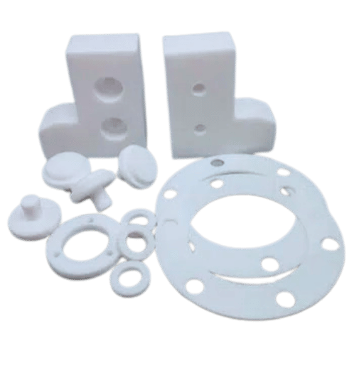
Shims, Gaskets, Bushings, Bearings, and PTFE (Polytetrafluoroethylene) coatings frequently have to work with rigid tolerances in various industries like aerospace, electronics, automotive, and medical. Usually standard tolerances for machining parts are between accepting some deviation of 0.001 to as high as 0.005 inches depending on the size, functions, and use of the component. However, some industries might have particular guidelines that are even more strict.
As an example, the aerospace industry needs tolerances up to 0.001 inches for some of their PTFE parts to be usable in high-performance and high-stress conditions. Medical applications like implants or lab equipment made from medical grade PTFE will often need similar tolerances as well as stringent biocompatibility. In the semiconductor industry, the use of PTFE parts in cleanroom processes places a great emphasis on precision, surface finish, and dimensional tolerances ranging even 0.0005 inches in some scenarios.
Processing PTFE can affect the dimensional stability given its rate of thermal expansion. For many other industries, optimum monitoring techniques include CMM inspection Optical measurement systems. On top of that, abiding by guidelines set by authorities like ISO 2768 for general tolerances or ASME Y14.5 regarding GD&T Geometric dimensioning and tolerancing ensures that the industry-specific requirements are met within the compliant boundaries.
Many elements that affect precision must be reflected upon while interpreting the tolerances of PTFE machined components. PTFE is a highly thermoplastic material and therefore has a significantly higher coefficient of thermal expansion than many metals, with ranges between 10 to 15 × 10⁻⁵ in/in/°F. This property makes it high in scope for deviation during the machining process. Hence, the temperature greatly needs to be controlled to mitigate deviations, both during and post the machining process.
In addition, the thermal expansion property also allows for easy deformation of PTFE due to its low elastic modulus, which ranges from 58 to 72 MPa. This creates the requirement of specialized tooling techniques and minimal clamping pressure So, cutting forces can be used without risking the integrity of thin wall structures while ensuring CNC machining tolerances are achieved. Additionally, specialized cutting tools are designed to have sharp edges and low cutting angles so that less stress is applied to the material and dimensional accuracy is attained.
Typically, machined PTFE components that routinely experience critical PTFE components critical to aerospace or medical industries usually have tolerances of about ±0.005 inches, Roughly in the order of micro inches. Prior internal stress relief processes such as annealing also greatly improve and ensure highly precise tolerances are achieved.
Employing inspection methods like laser scanning as well as non-contact vision systems and multi-axis CNC CMMs guarantees that manufacturers accurately accomplish the tighter tolerances specified for PTFE components. Highly accurate measurements can be taken even with difficult geometries using these methods. A deep understanding of PTFE combined with these advanced methods makes it possible to achieve the top levels of dimensional precision.
Meeting certifications for aerospace and other ultra-precise industries demand strict compliance to materials quality, manufacturing methods, and inspection processes. This encompasses the use of certified raw materials, compliance with procedures like AS9100 for aerospace manufacturing, and inspection of quality at every stage of production. Material and process traceability is crucial in demonstrating compliance with these regulations. Also, as a means of ensuring that components are repeatedly accurate about safety, reliability, and performance, collaborating with accredited laboratories and utilizing well-defined testing techniques is indispensable.
The need for tighter tolerances in PTFE machining can increase production costs due to the extra time, specialized equipment, and additional procedures needed to complete the task. Moreover, increased Precision Machining tolerations require more sophisticated machining instruments, increased caution during material handling, and more frequent quality control inspection which invariably increases operational costs. Despite this, overall cost efficiency can be maintained by streamlining production processes, utilizing appropriate machining methods for the specific case, and reducing material labor. Managing these factors appropriately keeps precision tolerations in check while limiting excess monetary expenditure for the services.
Preliminary steps of a CNC machine tend to be accurate but lack adequate consistency to reach tolerances, achieving improved tolerances in PTFE machining remains a reliable undertaking, as investing in advanced CNC machinery offers. Efficiency is greatly enhanced with the help of Advanced CNC technology. More so, advanced CNC machines minimize production time and material wastage, which increases efficiency altogether. Setting aside the initial capital investment, the positive ROI that comes from the increased accuracy, throughput, and lowered cost, makes such significant expenses worth it in the long run. Regardless of the margin of error, meeting those stringent tolerances is far simpler with the proper CNC machines.
The return on investment (ROI) for tight tolerance PTFE machining capabilities depends on return factors, these are the cost of technology-heavy machinery, achieving operational efficiencies, and the markup on the final product. Better tolerances allow for waste reduction, minimization of rework processes, and enhancement of the performance of the product which culminates in greater customer satisfaction and retention. Furthermore, specialized industries such as medical and aerospace which require high-precision components almost always have a premium, thus covering the most conservative initial investment. By offsetting the quality, efficiency, and marketability of the business with the acquisition cost, it is possible to have a favorable ROI.
A: The unique challenges of machining PTFE (polytetrafluoroethylene) stem from its specific material properties. PTFE has a great thermal expansion value which when combined with a low conductivity rate, results in the material deforming with pressure. These features pose specific challenges to the machining process such as the need to cover PTFE with sufficient cutting fluids to avoid overheating and the use of sharp feeding blades so as not to deform the material beyond the tolerance limits. To achieve desirable tolerances and surface finish, the cutting speeds and feeds have to be extremely precise.
A: The specifics of CNC machining tolerances are greatly affected by PTFE, particularly when it comes to unilateral tolerance. Because of its soft nature and capacity to change dimensions due to temperature variance, PTFE is known to react undesirably. The low friction can result in poor stability of PTFE, thus resulting in weakness during the cutting process. Furthermore, in order to attain tight tolerances, the temperate, tooling, and cutting parameters have to be regulated by the individual machinist as to accommodate for the excess PTFE softness.
A: Parts that are machined from PTFE have a typical tolerance range that is centered around specific machining procedures and the degree of complexity of the part. For PTFE machined parts, the typical tolerances are set at ±0.005” to ±0.010” (0.127 mm to 0.254 mm). Nonetheless, with adequate equipment and methods, these tolerances can be made tighter at ±0.002” to ±0.003” (0.0508 mm to 0.0762 mm). It should be acknowledged that because of PTFE’s unique material properties, achieving these tolerances is quite difficult.
A: In PTFE machining, CNC services maintain precision by: 1. Specialized tools for plastic machining are custom-made. 2. Proper fixtures are designed to reduce part misalignment. 3. The temperature of the environment is controlled. 4. Correct cutting speeds and feeds are employed. 5. Coolants are applied to control the generation of heat. 6. Dimensional changes are checked regularly during the machining operations. 7. Allow the workpieces to relax before undertaking final measurements.
A: Some of the notable benefits of machined PTFE parts are: 1. Exceptional chemical protection 2. Very low coefficient of friction 3. Very high-temperature tolerance 4. Electric insulator 5. Nonadherence to other surfaces 6. Reasonable abrasion resistance 7. Compliance with FDA requirements for food and medical uses These characteristics also enable it to be used in CT Scans, X-ray machines, and other equipment used in the food and medical industries.
A: When compared to other plastics, the machining process for PTFE is different according to: 1. Use of reduced cutting speeds to avoid overheating 2. Using sharper tools to ensure clean cuts 3. Changes in tools may be more frequent because PTFE is abrasive 4. More emphasis is placed on chip removal to avoid re-welding 5. The choice of coolant is very important because PTFE does not dissolve in many coolants 6. Sufficient post-machining holding time is frequently required to allow the material to relax.
A: When specifying tolerances for PTFE machined components, one should consider: 1. The application and the accuracy requirement 2. The part’s overall size and its complexities 3. Type of PTFE with a specific grade designation 4. In service, expected temperature range 5. Competence of the provider in question 6. Pricing for closer tolerances 7. The possibility of changes in dimensions after machining 8. Additional processes or treatments are needed.
A: These parts are typically used in: 1. Precision parts for chemical equipment such as valves, gaskets, and seals. 2. Semiconductor industry machinery such as wafer handling components (chuck, tray, etc.) 3. Specific parts of the Aeronautics industry like Teflon bushings and Teflon bearings and insulation. Medical implants reconstruction surgery parts and surgical tools for medical procedures 5. Specific parts of food processing plants. Non-stick cookware surfaces and gaskets and seals for various machines. 6. Parts of the automotive industry such as seals, bearings, and parts of the fuel system. 7. Electronics, such as insulators and components for devices operating in the high frequency range. PTFE is largely used for its unrivaled durability and thermal stability.
A: Manufacturers can use the following methods to ensure minimal defects when machining PTFE parts: 1. Apply rigid control measures during the different stages of the machining technology. 2. Control the temperature and humidity of the machining environment. 3. Use reputable suppliers that provide consistent PTFE material. 4. Periodically calibrate and service CNC machines and measuring instruments. 5. Have machinists who are trained in the modern methods of PTFE machining. 6. Use standardization in procedures for PTFE machining operations. 7. Use various technological operations of production for control and dimensional verification of produced parts.
1. Trimmed Surface Roughness Analysis and Productivity Cycles when Turning PTFE Polytetrafluoroethylene: A Comprehensive Approach to Optimizing The Machining Process of PTFE
Key Findings:
Method: The authors of this research have developed and tested RSM–response surface modeling for PTFE machining and surface trim roughness measuring which was followed by information optimization of the machining condition (Azzi et al, 2022, pp. 407-430).
2. Non-Dominated Sorting Modified Teaching–Learning Based Optimization for Multi-Objective Machining of Polytetrafluoroethylene (PTFE)
Key Findings:
Methodology: A multi-objective problem of the optimization of concrete parameters was solved with the modified teaching-learning-based optimization algorithm using experimental data gathered from machining PTFE(Natarajan et al., 2020, pp. 911 – 935).
3. Evaluation and Optimization of Surface Roughness and Metal Removal Rate Through RSM, GRA, and TOPSIS Techniques in Turning PTFE Polymers Dry Machining
Conclusions:
Approach: Narayanan and others (2019) examined and optimized the machining parameters using the surface roughness method, GRA, criteria for the choice of the most preferable alternative solution – TOPSIS (Narayanan et al., 2019).

Manufacturing processes are quite complex, and the choice of a production method is directly related
Learn More →
There are two major manufacturing methods for producing plastic prototypes that most people find useful
Learn More →
As a person involved or interested in the design and production of plastic components, it
Learn More →