

Manufacturing processes are quite complex, and the choice of a production method is directly related
Learn More →
CNC plasma cutting is a technique for rapidly and precisely cutting different metals. Like any other technology, it is not without its challenges. From cutting inaccuracies to consumable wear and tear, each problem must be solved to maximize performance, minimize downtime, and achieve optimum quality.
This post covers the nine most common issues related to CNC plasma cutting along with solutions and tips for operators ranging from poor cut quality, arc stability, incorrect pierce settings, and more. This post also serves as a guide on correcting the issues associated with improper pierce conditions and gives incisive details to guide proper incision conditions. After reading, you will not only have a sophisticated approach to the hurdles but also discover how to fine-tune your plasma-cutting dependence for impressive, neater results.
Lack of Details In Cuts Quality
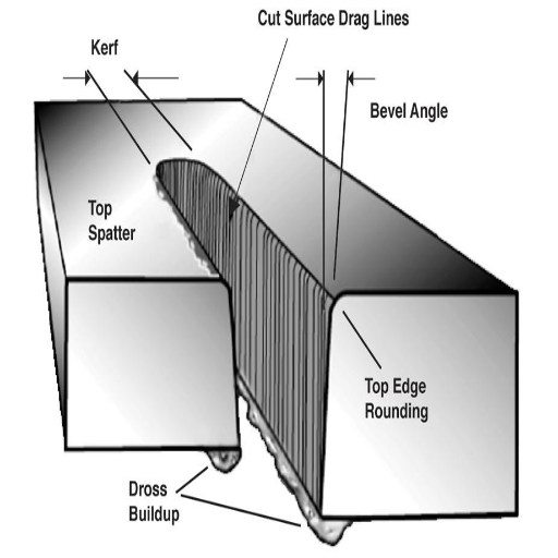
Troubles like non-standard edges, too much dross, or cuts that are not straight are usually made because of incorrect configuration, broken parts, and even lousy torch height. Parameters related to the material’s type and thickness should be maintained correctly.
Inconsistency of Acutely Produced Sparks
Broken electrodes, lousy grounding, or a power supply cause fluctuating arcs. Worn parts should be replaced regularly to avoid losing stability and flexibility.
Incorrect Shooting
Cutting through the material too quickly is associated with pierce heights that are too low or insufficient power levels. Set these variables and check the correct parts being used for the board.
By conducting a thorough diagnosis and tracing the root of each problem, it is possible to significantly improve CNC plasma cutting performance and achieve much cleaner and more accurate results.
The most common cause of poor cut quality in CNC plasma cutting is improper setup, used consumables, and wrong parameters. Let’s see how I tackle these issues in detail.
Poorly Defined Cutting Speed
First, I analyze the torch’s setting angle. If I notice a lot of dross on the edges, I know the speed setting is low, and if the sides are rough, the speed is way too high. Having done this for quite some time now, I rely on settings, and given the material and thickness, I am confident the speed will always be perfect.
Torch Height Adjustments
Once again, the torch’s angle directly correlates with the pre-defined parameters. Whether I am cutting too far into the material or very close to it, I try to strike a balance by using a height control system, which keeps my plasma cutting steady.
Consumable Parts Worn Out
Defective nozzles or electrodes often result in a weak or defective arc. My simple solution to this problem is to keep checking and replacing: with enough foresight, you will have precise cuts!
Tackling these factors will improve the precision and cleanliness of the CNC plasma cutting system.
To fix problems with inconsistent arc and uncontrolled arcing, the following procedure must be followed:
Check Input Power Stability
As stated earlier, ensure the power supply meets the machine’s requirements. Problems such as arcing instability can occur due to fluctuations in voltage, poor grounding solutions, and lack of sufficient grounding.
Recommended Voltage Range: +/—10% of the machine’s utilized input. For example, 220 volts plus or minus 20 percent for systems that operate at 220 volts.
Inspect Consumables
Broken nozzles and electrodes lead to dysfunctional arc stability; therefore, check the degree of consumables used. Components must be replaced if there is an absence of wear or deformation.
Electrode Life Expectancy: Average 8 – 10 hours when used commonly.
Nozzle Orifice Tolerance: The proper size must be configured for the amperage. For example, a 0.9 mm orifice for 40 Amps would be used.
Air Supply Quality And Pressure
Remove all moisture and ensure the air supply is clean and dry while regulating the pressure to the correct value. Remember that a lack of moisture or any other contaminant can lead to erratic arc behavior.
Recommended Air Pressure: 70 to 120 PSI based on rules provided by the manufacturers.
Air Filtration Level: At least 5-micron level to purify the air stream and ensure cleanliness.
Verify Cut Speed and Amperage
Setting a cut speed or Amperage that does not match results in a compromised arc. Settings must be adjusted to suit the material thickness and type one wishes to cut.
Recommended Amperage and Speed Examples (for mild steel):
10mm Thickness: 40A, 500 mm/min
6mm Thickness: 30A, 850 mm/min
Look over the Cables and Connections
Ensure torch cables, ground clamps, and connections are undamaged and properly tightened. Loose connections will disrupt the current flow.
By adopting these steps and observing the recommended technical parameters, you can significantly reduce the chances of experiencing erratic and uncontrolled arcing conditions during your plasma-cutting operations.
The premature wear of consumables is a common challenge within plasma-cutting processes that leads to more expenses and downtime. Knowing the causes and enforcing the proper measures can increase the consumables’ life and the cuts’ efficiency.
Common Causes of Premature Wear:
Improper Gas Pressure or Flow
Too low or high gas pressure will result in less than optimal wear on the consumables. Set the gas pressure as suggested by the equipment manufacturer.
Gas Pressure for Cutting Thicknesses:
6mm Thickness- 75psi
10mm Thickness – 80psi
Regulators should always be checked to ensure that the gas is flowing uniformly.
Incorrect Amperage Settings
In most circumstances, improper amperage levels will create too much heat, which will cause unreasonable wear on the bulldozer and upper levies. The material thickness should determine the amount of amperage.
Recommended Amperage:
6mm Thickness – 30A
10mm Thickness – 40A
Piercing Too Close
The piercing process should not be done near the material; otherwise, it will compel the molten metal to be ejected upward, pouring more stress onto the bulldozer head. Because of this, the proper stand-off distance must be observed.
Recommended Standoff Distance: 1.5 to 3mm.
Neglecting Regular Maintenance
Dirt and spatter chlorides can affect the torch’s performance. Regularly cleaning and maintaining the torch parts, such as the nozzle electrodes and shield, will ensure their dirt-free condition.
Most Effective Steps to Avert Early Damage:
Use specialized, compatible consumables for your plasma cutter.
Ensure air filters are on the cutting machine so moisture or other particles do not reach the torch.
Preheat the torch to its operational temperature before cutting, especially for thicker materials.
Create a regular consumable inspection routine and inspect parts for wear indicators rather than waiting for failure during operation.
Following these technical measures, slowing down, and assessing wear patterns will ensure minimal premature wear, thus maintaining operational functionality and expenditure.

To effectively address issues with the plasma cutter torch, confirming that the power supply is charged and the machine is taking the voltage is crucial. Check the consumables for any damage or wear and tear, as faulty parts can lead to cutting problems. Ensure the torch is completely adjusted, and all parts are assembled. Look for the correct quality and pressure in the air supply; oil and moisture can significantly affect operations. Lastly, check out the manufacturer’s manual to know what error codes the machine gives or specific steps, such as diagnostics. By dealing with these issues systematically, performance problems are frequently solved, and the cutting efficiency is restored.
As far as I’m concerned, the issues with torch height control are usually attributed to incorrect voltage values and faults within the system. To begin with, verify that the torch height control is calibrated correctly and can maintain a standard arc voltage. This allows cutting to be performed more efficiently. Also, inspect the sensor, checking for any breakages, misalignments, and errors that might affect the sensor’s accuracy. Furthermore, check the wiring and connections for any loose or missing cables. If the issues persist, in some cases, replacing the control c software or performing a factory reset can help. These instructions should help in solving most issues related to torch height control.
Both electrodes and nozzles are prone to changing a cut’s quality and the equipment’s efficiency. Improper gas flow, contamination, and super high amperage are usually the causes. When they arise, set the gas pressure at the machine’s recommended range- typically from 60 to 120 PSI. Ensure the amperage is within the rated capacity of the nozzle. Anything above will cause it to overheat and the equipment to deteriorate rapidly. Cleaning both components regularly ensures any dirt that disrupts arc stability is removed. Pitting or whittling are signs of wear and should be looked out for. The nozzle and electrode should be replaced once any form of degradation is sighted to achieve the best cutting output.
Gas and coolant flow issues can essentially impact a plasma-cutting system’s efficacy and life cycle. Fixed gas flow leads to proper arc stability, accurate cuts, and low chances of spillage. Spillage and poor arc results when there is too much or too little gas, alongside low-quality cuts and rapid damage to consumables. Between 60-120 psi is the optimal range; however, please check the system manufacturer’s specifications. Remember to use soap and water when checking the connections since it is the best way to confirm no leaks.
Coolant flow is significant even for liquid cooling systems for torch temperature control. Confirm that the liquid levels are sufficient and that the flow rate meets the machine’s requirements. A flow of 1-2 GPM is considered normal for industrial plasma cutters. Insufficient or erratic coolant flow can lead to excessive overheating, harm to internal parts, and lower cut effectiveness. Routine examination of filters and coolant passages for blockages or foreign matter accumulation is necessary to maintain efficient cooling system operation.
When you resolve these parameters: gas pressure, connection tightness, coolant levels, and flow rate, it is possible to reduce the problems associated with gas and coolant flow and ensure that the plasma cutter is used at its maximum potential and longevity.
Inadequate air pressure can lead to poor cutting quality, difficulty piercing materials, and rough edges. Moisture in the air supply can internally damage components, shorten the life span of the torch, and degrade the precision of the cuts. Insufficient air pressure can also come from the air tank that serves the cutting device, which causes a weak air supply or moisture build-up on top of inconsistent airflow. Deversed edges, hard-to-complete cuts, and an unstable plasma arc in the torch result from ICF or insufficient airflow. Always aim to supply higher pressure than is needed, filtering and drying where necessary, and don’t forget to schedule maintenance.
Meeting the minimum specified parameters is a critical upgrade your air compressor should undergo. If these are ignored, the quality of the plasma arc will be severely diminished, and the resulting cuts will become weak or even forced. During the cutting process, these problems may stall the device entirely.
Essentials to Consider to Decrease Low Air Pressure and Unbalanced Flow:
Through needing to heat the plasma cuttings, the air pressure range ought to follow the supposition set by the system. Between 65 and 120 PSI is ideal for all your air compressors (but always check the user’s manual first).
Flow Rate: The air compressor must deliver an uninterrupted air supply suitable for the plasma cutter’s specifications. Depending on the machine’s size and capacity, the compressor usually delivers 4 to 7 SCFM at 90 PSI.
Air Quality: Make a filter to eliminate contamination and moisture in the air supply line and ensure the air is clean and dry.
Prevent airline and connection leaks, confirm a suitable compressor size, and provide reliable and consistent maintenance to maintain airflow. If these instructions are followed, cutting accuracy will improve, and the equipment’s life cycle will be enhanced.
Contaminated compressed air is propelled from assorted sources, including environmental particles, degraded lubrication, airline rust, and water vapor. Dirts, oils, and moisture are infamous as contaminants and system performance indicators. Clogging, corrosion, and damage are some conditions that put pneumatic tools at the mercy of inadequate filtration and drying systems.
Key Parameters and Solutions
Particulate Contamination
Cause: Dust, debris, and rust are pollutants that enter the system due to the environment or pipe corrosion.
Solution: Ensure that particulate filters are installed first to eliminate debris as small as 1 micron and protect downstream devices.
Oil Contamination
Cause: Oil from lubricated compressors and poor system maintenance contaminates the oil.
Solution: Coalescing filters with 0.01 ppm efficiency should be used while removing oil aerosol and vapor.
Moisture Contamination
Cause: Humidity in intake air and insufficient dried air contaminates moisture.
Solution: Reduce dew point using refrigerant dryers. Desiccan dryers can be used where extreme conditions of 40C are required.
These air quality measures and prescribed filtration will minimize contamination, improve equipment performance, and enable the system to achieve optimum performance. Validation of the compressed air systems should always start with consultation with device manufacturers.
While maintaining air filters, I clean and replace them regularly. In maintaining the filters, I look for clogs, his, or damage at intervals recommended by the manufacturer, typically monthly or quarterly. For reusable filters, I do follow some procedures such as washing or using compressed air to clean them. If the filters reach their lifespan or have been damaged beyond repair, I replace them on time to ensure that the quality of air and the efficiency of equipment are not compromised. These actions help me retain the quality of my compressed air system with minimal downtime.

The right tools must be selected and adequately maintained to achieve optimal cutting speed and efficiency, while efficient operational practices should be applied. Start by selecting the appropriate cutting tools and materials tailored to the task. Maintain tools within the range that can often be sharpened and regularly check them to ensure that precision is accurate and resistance is lessened. Adjust the power of cutting tools, for example, the speed and depth of cut relative to different materials, to make the work smoother and faster. Where feasible, invest in new, more powerful machines or automation to improve both the speed and constancy of the processes. Tools should be kept in clean operating conditions, and the equipment should be lubricated to avoid excessive heating of the tool or machine and to cover the tool’s longer lifespan, improving efficiency.
Cutting Speed
Adjust the cutting speed according to the component’s material:
Aluminum: 300-500 SFM (Surface Feet per Minute)
Steel (Low Carbon): 100-200 SFM
Hardened Steel: 50-100 SFM
Feed Rate
The tool diameter and the material’s hardness should determine the feed rate:
Small Tools (<1/4 inch): 0.001-0.003 inch/tooth
Medium Tools (1/4 to 1 inch): 0.005-0.010 inch/tooth
Extensive Tools (>1 inch): 0.010-0.020 inch/tooth
Depth of Cut
Always strike a proportionate balance between efficiency and the machine load:
Roughing Passes: 50-75% of the tool diameter.
Finishing Passes: For better accuracy, 5-20% of the tool diameter.
Tool Material and Coatings
For general machining, use carbide or high-speed steel (HSS) tools.
For demanding components such as stainless steel, use tools with TiAlN or TiCN coatings due to their heat resistance.
Cooling and Lubrication
Make sure that coolant flows consistently to prevent overheating.
For general-purpose machining, use water-soluble coolant, but for high accuracy or high-temperature jobs, use oil-soluble coolant.
When these conditions are comprehensively integrated into specific materials, optimal cutting conditions and tool life can be achieved.
Arc stretching generally occurs when there is a lack of balance at the process parameter stage or during equipment setting, resulting in unstable arcs and low welding efficiency. Below are key considerations that should be examined while solving and managing arc stretching.
Electrode Type and Size
The electrode should be selected based on the material and welding process.
Use a small diameter electrode for tighter arcs (for example, 1/16”, or 1.6 mm), achievable precision and stablility during welding are ensured.
Voltage and Current Settings
The voltage that is set should accommodate the recommendation. Too high a voltage will stretch the already elongated arc.
Recommended values are:
TIG Welding (DC) 10-20V
MIG Welding (Steel) 16-22V
The current should correspond with the thickness of the material and size as well as the electrode type.
Steel plate 1/16” (MIG) ~120-150A
Aluminum 1/8” (TIG) ~125-200A
Workpiece Distance and Torch Angle
Adjust and maintain a fixed work distance to the size and type of the electrode. This is about 1/8”-3/16” (3-5 mm) from the tip of the electrode to the workpiece.
Angle the torch to approximately 15-20° from the vertical position to smooth the control of the arc.
Gas Flow Rate and Type
Make sure proper shielding gas flow to prevent destabilization of the arc;
TIG Argon 15-25 CFH
MIG Argon-CO2 mix 25-35 CFH
Pure Argon can be used for non-ferrous metals, and an argon-based mix can be used for ferrous metals.
The Speed and Method of Travel
To keep an arc at a steady amplitude, you must adjust the travel speed of the torch:
An arc that is too slow will increase the input of heat and the length of the arc.
An arc that is too quick will reduce the stability of the produced arc.
Use techniques like weaving or constant movement forward to achieve consistency in the arc.
Some of these modifications can reduce the arc’s stretching, resulting in a better weld and increased consistency. Also, routine equipment maintenance and proper parameter setting are needed to obtain reliability.

Torch Misalignment—If torches are not appropriately aligned, inaccurate cuts and uneven edges will result. Checks and calibrations need to be performed regularly.
Pierce Height Issues—An incorrect pierce height setting results in wasted consumable parts or machine cuts below standard. Height control systems should be used for accuracy.
Consumable Wear—Used electrodes or nozzles lead to lower cut precision and more excellent dross formation. Consumables must be replaced regularly to maintain the desired quality.
Poor Air Quality – Dirty air or insufficient air supply gives rise to poor precision cuts and edges with uneven arcs. Provide sufficient clean air to achieve desired levels.
Software Errors – Glitches in design files created by CAD or CAM software problems can hamper practical usage. Always ensure that the software is updated and the files are not corrupted.
Regular maintenance, combined with solving issues as they arise, can greatly improve the performance and quality of cuts.
An alignment error can result in skewed cuts, loss of accuracy across the board, and overworking the machinery. It is critical to start by addressing both calibration and alignment. In doing so, the following steps are key to performing precise cuts as well as ensuring the optimal performance of the machine:
Torch Alignment: Make sure to use the cutting surface to which the torch is perpendicular. It is also best to avoid beveling, so using laser guides or alignment tools can serve as an excellent means of cutting toward accuracy.
Gantry Calibration: When smoothing out the gantry’s movements, ensure it is as free of struggles as possible. Regularly checking the belts, rollers, and guide rail is also a good practice to mitigate the risks of them wearing out or lacking tension. Remember to consistently sustain a positional tolerance of 0.1 mm if the task is exact.
Table Leveling: Confirm that the surface of the cutting table is level at all areas, otherwise it will distort the material position and cut quality.
Calibration of Cutting Parameters:
Arc Voltage: Ensure the arc voltage is set correctly based on the thickness. If the material is milled steel around 3/8 inch thick, a setting of 120 to 140 volts should be perfect.
Cutting Speed: Confirm that it is appropriate for the material regardless of whether it’s being served in inches per minute (IPM).
Torch Height: When plasma cutting, keep a height control system handy so that an ideal distance above the material is 0.060-0.080.
Inspection of Encoder Feedback: Check in on the motor encoder or position digital sensors to ensure that feedback is precise and coordinates are synchronized with the movement.
Regularly enforcing this alignment and conducting calibration tests will lessen operational glitches while consistently achieving high-quality outcomes.
A CNC plasma cutter workflow can be maintained with adequate software and control systems troubleshooting. Here are important considerations and steps required to fix common problems:
Audit The Communication Flow Of Hardware And Software
Check if the CNC controller communicates with the software. Ensure there are no loose or damaged cables, replace outdated drivers, and ensure the correct communication port is enabled in the software’s settings.
Review Error Codes or Logs
Diagnostic codes and error logs can provide critical information on the errors occurring in the system. These codes can be compared with the machine’s manual or the manufacturer’s website for appropriate actions.
Evaluate Configuration Settings
Misconfigured settings can cause operational soft errors on the CNC machine. Check operating parameters such as feed rate, cutting speed, and acceleration and deceleration. Depending on the size of the material, the general baseline cutting speed for mild steel on CNC plasma cutters is between 50 and 150 inches per minute.
Reinstall Software Or Update It
Outdated software can create compatibility problems. Ensure the CNC controller software is on the latest version available. If the issues are still common, uninstall and reinstall the software, but ensure the user’s configuration files are maintained.
Adjusting Motion Control Systems
The above-stated discrepancies in alignment and accuracy can often be solved by recalibrating the control system. Ensure the following are in check:
Resolution: Ensure the stepper or servo motor has the appropriate resolution to deliver the required accuracy. In the case of virtually every CNC application, this means 0.001” or finer.
PID Tuning: For the PID controller, adjust the proportional and integral settings and derivate settings for better oscillation dampening and smoother movements.
Checking License And Activation Keys
Specific CNC software may require active licenses or keys not provided by default. Check whether the software license is valid or has expired.
Following these steps can minimize downtime while maximizing cutting efficiency. Many manufacturers and online forums offer additional insights that can help solve these issues.

For an effective and efficient performance of a plasma cutting machine, carry out the following strategies:
Regularly Inspect and Replace Consumables
Regularly check for consumables, such as electrodes and nozzles, examine their condition, and replace them periodically so that the torch does not incur damage and the quality of the cuts is maintained.
Clear Debris from the Torch
Remove the torch regularly to extend the life of its components and remove debris and spatter that hinder its proper functioning.
Air Supply Must be Clean and Well Maintained
The air quality must be excellent, and the pressure and moisture level must be controlled to ensure this. Moisture separators and filters must be utilized to ensure that the quality of the cuts is not compromised.
Secured Cables and Connections
Proper supervision of the cables, hoses, and connections must be in place to fix any faulty or loose fittings that hinder smooth working.
Update Software and Firmware.
Updating the machine’s software regularly ensures that the previously documented errors are corrected and that new, improved features are incorporated.
Routine Calibration
Like most machines, plasma cutting machines operate optimally when regularly calibrated for the accuracy and precision of the cuts they execute.
These strategies must be followed to achieve better and more consistent results with plasma cutters.
Consistently replacing parts is crucial for maintaining performance standards and improving cut precision. I regularly conduct a wear check on electrodes, nozzles, and shields. When these parts are damaged or affecting cut quality, I replace them. Replacing these components ensures the proper functioning of my plasma cutter and helps me get reliable cuts every time I use it. Proper replacement and tracking help me mitigate expensive repairs and downtime.
To prevent long-lasting performance issues, it is essential to properly clean and inspect the plasma torch. Start by detaching the torch from any power source to ensure safety. Use compressed air to discharge big chunks of dirt and dust out from the body of the torch and its cooling passages. Look for wear, damage, and blockages in the torch head. Also, look at the retaining cap and nozzle since the buildup in these areas can severely impact performance. Don’t forget to examine the O-rings because damaged O-rings can leak gas and reduce overall cutting quality. Lastly, ensure that there is no connection corrosion and that everything is appropriately secured.
To ensure the best performance of your plasma cutter, regularly maintain it, following the manufacturer’s specifications of airflow pressure, typically between 60 and 120 psi (4.1 to 8.3 bar). Clean the plasma cutter regularly to ensure no debris is stuck in the inner workings of the cutter, as incorrect airflow pressure can severely affect the performance of the plasma cutter. Following these guidelines will get you precise cutting every time and will increase the durability of the cutter’s torch.
For the accessories related to the cutter, I ensure they are free of debris before storage to avoid corrosion that may damage them during storage. They are stored in a protected area away from extreme temperatures and moisture. Consumables such as nozzles and electrodes should be stored in sealed boxes or original containers to prevent contaminants. For transportation purposes, all parts of the cutter are stored in protective cases to avoid physical impacts that could damage them.
General guidelines I make sure to follow are checking if the air compressor’s pressure is held at recommended levels (60 to 120 psi, 4.1 to 8.3 bar), pads wires together to gas hoses and checks for wear and tear before usage, and ensuring gas hoses and other connectors are intact. These safety measures guarantee the effectiveness of the plasma cutter over the years.
Ensure your safety first when diagnosing issues with a CNC-operated plasma cutter. Start out by removing the cutter from its power source. As a rule of thumb, remember to use the relevant personal protective equipment (PPE) like safety goggles, gloves, and fire-resistant garments to avert injuries caused by sparks and flying debris. Make sure you are not exposed to harmful fumes. The workspace should be well-ventilated. Check for damage and wear before touching the cables, hoses, and connectors. Also, remember to consult any safety protocols specified by the manufacturer in the user manual. These tips lessen risks to keep you and your surroundings safe.
Working a CNC machine plasma cutter presents hazards, which include potential burns, eye injury, and exposure to electric shock or intense noise. Properly chosen PPE is significant in mitigating risks and meeting industry standards. This is a simple outline of necessary protective equipment:
Safety Goggles or Welding Helmet
Protects the eyes from intense light, sparks, and small flying objects.
Recommended standard: eye protection compliant to ANSI Z871.1
Flame-Resistant Clothing
Suitable for FR-rated cotton or any other fabrics such as AR/FR materials.
Defends the body against sparks and molten metals.
Heavy-Duty Work Gloves
Protects the hands from sharp edges, as well as heat and sparks.
Fabric suggestion: gloves made from leather that is resistant to high temperatures.
Steel-Toe Boots
Protects feet while working from dropped objects and slipping while at work.
Meets the legitimate standards set out for ASTM F2413-18.
Hearing Protection
It lessens listening to clear sound produced by the machine.
Use plugs or muffs and NRR 22 or greater.
Respiratory Protection
Stops the worker from swallowing toxic fumes and small particles during cutting.
A respirator with an N95 filter or greater is recommended. If ventilation is insufficient, PAPR may be necessary.
Meeting these guidelines for the PPE used when working or troubleshooting a CNC plasma cutter will provide excellent results while ensuring safety. Remember to check for damage and proper fitting of all gear before use.
Equally important is electrical safety when using CNC plasma cutters, as neglecting it may often lead to mishaps and equipment failures. The following are considerations to keep in mind:
System Grounding
As per manufacturer recommendations, ensure the system’s grounding is in place. Grounding relieves the user and system from electrical shocks and stabilizes the system. The grounding regulations are in accordance with OSHA and NFPA 70 (National Electric Code) standards.
Power Supply
Always ensure the power supply voltage corresponds with the machine’s rated voltage. If there is a mismatch, overheating or malfunction may result. Depending on the model, most CNC plasma cutters operate best on an input voltage of 110V, 220V, or 400V.
Examine Power Connection
Frequent examination of the power cords, plugs, and sockets for cutting, fraying, or wear is essential. Any damaged component should be replaced as it may trigger short circuits or electrical fires. Heavy-duty industrial-grade power cords that comply with IEC 60245 regulations should be utilized.
Electrical Protection
Appropriately rated circuit breakers (or fuses) should be used to secure monitoring and control circuit supply voltage. For plasma cutters, protection may range from 30A to 50 A, depending on the machine size and power draw.
Avoid Overloading Circuits
Avoid using extension cords and plugging multiple high-power devices into the same outlet to avoid overloaded circuits. Dedicated circuits for the plasma cutter should be used instead.
Turn Off Power During Maintenance
Cleaning, maintenance, or troubleshooting should never be done while the device is plugged in. Disconnect the machine from the power source. This eliminates unexpected electrocution risks.
Work In A Dry Environment
In the workstation, moisture should be eliminated as much as possible. Avoid exposing your work area to water as it increases the risk of electrical shocks. Anti-static mats or insulating materials may be utilized if necessary.
These recommendations lower electrical threats when operating CNC plasma cutters. It is equally important to do regular inspections to ensure safety throughout the usage period.
It is crucial to have proper ventilation and fume extraction when using CNC plasma cutters to reduce the health issues associated with toxic fumes and particulates. Plasma cutting is capable of generating ozone, nitrogen oxides, and metal particulates that can be damaging to one’s respiratory health and the environment in the absence of effective control measures.
Fume Extraction Systems
To remove and capture fumes, use a downdraft table or overhead hood connected to a filtration system. Such systems must supply negative pressure and sufficient airflow to satisfy the cutter’s ventilation requirements. For example, small to medium-sized plasma cutters require 800-1200 CFM of airflow.
HEPA and Activated Carbon Filters
HEPA filters are ideal for blocking fine particulates, while activated carbon filters eliminate harmful ozone gas in the fume extraction unit. The filters need to be replaced periodically to maintain good quality.
Room Ventilation
The workspace should also feature an air circulation system that delivers at least 6-10 air changes per hour in the industrial setting to ensure robust ventilation. This also helps reduce the concentration of residual fumes that local extraction systems fail to capture.
Adhering to Safety Regulations
Ensure that the employees follow guidelines set out by Cal/OSHA (e.g., Cal/OSHA 1910.1000 Air Contaminants) so that fume concentrations remain under permissible exposure levels (PELs). Periodic air checks should be conducted to confirm compliance.
Personal Protective Equipment (PPE) Engineering Controls
When working in situations where ventilation will not capture all fumes, don N95 respirators or specialized welding helmets when additional protection is needed.
Implementing these measures carefully prevents potential hazards while maximizing the productivity and durability of CNC plasma cutting tools through a cleaner setting. Regular system maintenance and monitoring will help you achieve optimal performance.
Leading CNC Metal Machining Provider in China
A: The most common CNC plasma cutting issues include uncontrolled arcing in the plasma chamber, inconsistent cut quality, premature consumable wear, difficulty in piercing thick materials, incorrect cutting height, arc instability, dross formation, kerf width variations, and problems with the plasma cutter software. Understanding these issues is crucial for efficient troubleshooting and maintaining the optimal performance of your plasma-cutting machine.
A: If your plasma cutter is not arcing, it could be due to several reasons. Common causes include worn consumables, incorrect air pressure, faulty torch components, or issues with the power source. Check your consumables for wear, ensure proper air pressure, inspect the torch for damage, and verify that the power source is functioning correctly. If the problem persists, consult your plasma cutter troubleshooting guide or contact a professional technician.
A: To improve cut quality, focus on optimizing your cutting process. Ensure you use the correct cutting speed, amperage, and height for the material thickness. Maintain proper consumables and regularly clean your plasma cutting machine. Adjust gas flow and pressure according to manufacturer specifications. Additionally, consider upgrading your plasma cutter software for better control and precision. Avoiding standard CNC plasma cutting mistakes like cutting too fast or using incorrect parameters can significantly enhance cut quality.
A: Excessive dross formation is a common plasma cutter problem often caused by incorrect cutting speed, improper height, or worn consumables. If you’re cutting too slowly, it can lead to more dross accumulation. Conversely, cutting too fast can also result in dross. Ensure you use the recommended cutting parameters for your specific material and thickness. Regular maintenance of your plasma system, including replacing worn consumables, can help minimize dross formation and improve overall cut quality.
A: Arc instability is a common issue in plasma arc cutting. To troubleshoot, first check your consumables for wear and replace if necessary. Ensure proper air pressure and gas flow according to your plasma cutter’s specifications. Clean the torch and check for any damage or blockages. Verify that your work clamp has a good connection and that your power source is stable. Check the torch height control system for proper functioning if using a CNC plasma machine. Addressing these factors can help stabilize the plasma arc and improve cutting performance.
A: Signs of worn consumables in a plasma cutting machine include decreased cut quality, difficulty starting the arc, unstable arc, increased dross formation, and wider kerf width. You may also notice visual wear on the electrode or nozzle, such as pitting or enlargement of the orifice. If your plasma cutter keeps experiencing these issues, it’s likely time to replace the consumables. Regular inspection and timely replacement of consumables are essential for maintaining optimal performance and avoiding common plasma-cutting issues.
A: To prevent uncontrolled arcing in the plasma chamber, ensure proper maintenance of your plasma system. Regularly clean the torch and check for any damage or wear. Replace consumables as needed and verify that they are correctly installed. Maintain proper gas flow and pressure, and ensure your air supply is clean and dry. Avoid using your plasma cutter in damp environments or on wet materials. If uncontrolled arcing persists, consult your plasma cutter troubleshooting guide or seek professional assistance to diagnose and resolve any underlying issues with your plasma cutting machine.
A: Cutting height plays a crucial role in plasma cutting quality. The optimal height used for cutting varies depending on the material thickness and the specific plasma system. If the cutting height is too low, it can cause premature wear of consumables and potentially damage the torch. If it’s too high, it can result in a broader kerf, more dross, and reduced cut quality. Many modern CNC plasma cutting machines include automatic height control to maintain the optimal distance between the torch and the workpiece throughout the cutting process. Properly setting and maintaining the correct cutting height is essential to avoid typical plasma cutting issues and achieve high-quality cuts.

Manufacturing processes are quite complex, and the choice of a production method is directly related
Learn More →
There are two major manufacturing methods for producing plastic prototypes that most people find useful
Learn More →
As a person involved or interested in the design and production of plastic components, it
Learn More →