

Manufacturing processes are quite complex, and the choice of a production method is directly related
Learn More →
Perpendicularity tolerance is a fundamental characteristic in the geometric dimensioning and tolerancing (GD&T) system that governs the position of features on mechanical components. In this publication, we’ll discuss the comprehensive structure of perpendicularity tolerance, its limits, application, interpretation, and most importantly its relevance in the design and manufacturing stages. Readers will understand how perpendicularity relates to feature sizes and orientation controls, and learn about the fundamental aspect of modern quality assurance in engineering components. This information is crucial for designers, engineers, or quality control personnel striving to enhance performance of intricate mechanical systems.
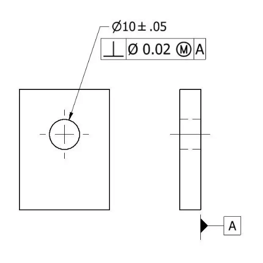
Perpendicularity tolerance is a type of GD&T control that sets the maximum permissible discrepancy from the perpendicular to a datum surface for a given surface, axis, or feature. The tolerance is often utilized to ensure that components have their angles set relative to one another, as such relationships are critical for assembly and disassembly. The features or parts with uncontrolled attributes perpendicularity controlled are usually defined by a three-dimensional zone within which the controlled feature must be contained. In most cases as illustrated in technical drawings, these features are represented by a feature control frame with perpendicularity symbol, accompanying the value of its tolerance and the datum reference which it relates to.
In engineering, perpendicularity tolerance is measured in micrometers (µm) or thousandths of inches (mils) based on the unit system of the design document. The value of the tolerance characterizes the area of sensitivity of the surface, axis or feature in relation to its corresponding datum – what is their orientation with respect to the perpendicular position.
In the case that a perpendicularity tolerance of 0.02 mm is set to Datum A, this indicates that the controlled surface or axis has to be fully contained within a cylindrical tolerance zone of 0.02 mm diameter, which is positioned at a right angle to Datum A. Such accuracy is important in precision mechanical assemblies, since any deviation from this value will contribute to parts being misaligned and thus not function properly or lead to reduced performance.
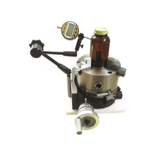
The type of measurement used takes into account the feature being analyzed. For flat surfaces, perpendicularity is usually checked with a height gauge and a surface plate, while cylindrical features are checked with CMMs for precise measurements. The data collected is critical in guaranteeing that certain manufacturing steps yield parts that conform to the expected design requirements that enable precision and dependability in engineering processes.
The limits of tolerance in a mechanical design is dependent on the requirements imposed on parts and their intended functionality. Here are the various kinds of tolerances with their descriptions:
Example data points:
Linear measurements can have a variation of ±0.01 mm for detailed components.
Standard tolerances for less significant measurements is estimated to be about ±0.1 mm.
Focuses on the maximum deviation allowed in a part’s geometry that does not involve a size parameter, including, but not limited to flatness, circularity, and parallelism.
Example limits include:
A flatness tolerance could define a permitted difference of 0.005 mm.
Parallelism with respect to some defined axis can be ±0.02 mm.
Defines the maximum limit of variation in measured angles.
Example ranges:
Some critical mating parts can be assumed to be allowed an angular variation of ±0.1°.
Some general purposes are allowed possible variations of an angle up to ±0.5°.
Regulates the accuracy of the predetermined shape of the component.
Example allowances:
The circularity has a possible deviation of 0.003 mm for highly precise parts.
Straightness controlled is mostly as per estimates and depend on the purpose.
Establishes the precise position of a feature in relation to a datum.
Sample criteria:
Positional accuracy for assembly-sensitive components may need allowances of no greater than ±0.02 mm.
Specifies the degree of smoothness or roughness of the surface of a part.
Common criteria:
Highly polished surfaces with Ra (Roughness Average) values of 0.4µm.
Standard Ra values of 3.2µm for machined finish.
In regard to the data and considerations of these tolerance types, mechanical design assures that parts will perform reliably and effectively within required operating conditions.
Geometric tolerances are the most important aspect of manufacturing since they decide the allowable amount of variation of a part’s form, contour, and its orientation and location in space. These tolerances are critical because they allow proper fitting of components and their correct functioning without undue overlap or obstruction. Manufacturers are able to greatly improve consistency, reduce rework during assembly, and increase the reliability of the product by minimizing the amount of deviation allowed.
Perpendicularity tolerance guarantees that a feature, such as a surface or axis, is at an angle of a surface or axis perpendicular to a specified datum. The tolerance zone for perpendicularity is most commonly a cylindrical or planar volume in which a feature has to be in order to conform to the design. For an axis, the tolerance zone is given as a cylinder coaxial to the datum axis. The diameter of the cylinder is equal to the specified tolerance.
Let’s consider an example for better understanding.
Feature: A cylindrical hole with a perpendicularity tolerance in a base plate for the hole.
Specified Perpendicularity Tolerance: ±0.02 mm.
Tolerance Zone: A cylindrical volume with 0.02 mm radius which is concentric to the hole`s nominal axis.
Notable advantages are:
Improved Assembly Precision – By minimizing angular deviation, alignment problems during assembly becomes less problematic.
Enhanced Product Functionality – Confers assurance that the parts move as intended, especially for mechanical parts that have movement restrictions.
Consistent Manufacturing Processes – Improved angular control reduces variability within production batches.
Some of the instruments needed to define and quantify perpendicularity tolerance are surface plates, height gauges, and CMMs (which are powerful measuring machines). These measurements help in meeting the design purpose and eliminate the chances of functionality breakdowns in the product’s end stage.
As a datum, the reference frame from which perpendicularity is measured is crucial because the specific feature being looked at needs to conform to certain requirements. Consider for instance a hole on a machine part that is required to be perpendicular to a surface. The surface is taken to be the primary datum A and all other measurements are taken with respect to it. With a CMM, the machine rotates about A, thus measuring how far out of alignment the angle is with respect to the surface being scanned.
Design Requirement: The machined hole is to be within perpendicularity tolerance of plus or minus 0.02 mm about Datum A.
Actual Results – Measurement Results (Sample Set):
Sample 1: 0.015mm
Sample 2: 0.018mm
Sample 3: 0.016mm
Sample 4: 0.019mm
Compliancy Rate: All samples , 100%, meet the set tolerances.
The provided information highlights the need for precise datum setup and measurement to conform to tight geometric tolerances. Consistent and reduced defect rates across production batches can be achieved through well-defined datum references.
Mechanical elements highly rely on axis perpendicularity. Proper perpendicularity is critical in achieving intended angular alignment during assembly to avoid misalignment and its negative impacts on wear and operational efficiency. Specified tolerances are essential for reliable products and for extending the longevity of assemblies.
In mechanical systems a datum is a reference point or surface used for ensuring perpendicularity are achieved. It provides a specific framework from which precise measurements and tolerances can be effectively controlled. For example, let’s say a certain cylindrical shaft has to be perpendicular to a baseplate. The baseplate is the datum, and all perpendicularity measurements of the shaft are taken in reference to this surface. That way there is no confusion and consistent manufacturing is maintained from batch to batch.
Example Data:
Shaft Diameter – 50 ± 0.05 mm
Perpendicularity Tolerance – 0.02 mm with respect to the datum baseplate
Surface Flatness of Datum – 0.01 mm
With such clear definitions, it is possible for engineers to design the shaft in such a way that it will truly fulfill its purpose after assembly. The analysis of perpendicularity deviations demonstrates other systematic errors such as: angular offset or protrusion/ recess of surfaces that can be remedied by enhancing machining or better calibration tool changes.
In precision engineering processes, the perpendicularity of a surface must be maintained within given tolerances to avoid deviations resulting in assembly dislocation and faulty mechanical functioning. For example, a perpendicularity tolerance of 0.02 mm can be maintained without causing excessive angular displacement of motion along rotational or linear systems. These tolerances can be measured and verified with great accuracy using advanced metrology tools like coordinate measuring machines (CMMs) and laser scanners. Also, automated machining processes with feedback loops can easily correct errors during manufacturing processes to consistently meet specified tolerances.
For the achievement of precision in perpendicularity measurement, the tools and techniques utilized differ based on the requirements for accuracy and the measurement complexity of the component. A frequently employed tool is the Coordinate Measuring Machine (CMM), which can measure with an accuracy of ± 0.001mm. A CMM measures by probing the surface on the object and comparing the measured coordinates to the specified geometric design. On the other hand, lasers scan parts, creating a point cloud with non-contact modalities, enabling the analysis of parts’ perpendicularity over intricate surfaces.
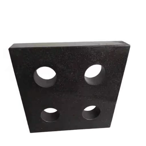
Another method is that of optical comparators, which allow for angular inspection by magnifying the component profile and visually examining it. In high-production surroundings, automated systems with real-time feedback control loops are used to check the perpendicularity in the machining process to ensure that the tolerances are fulfilled. Moreover, less accurate but reliable tools for checking perpendicularity are specially designed for less complicated constituents by angle plates and square gauges.
Tool: Laser Scanner
Accuracy: ±0.005 mm
Use Case: Measurement of fragile or complex surfaces without putting effort on the surface.
Tool: Coordinate Measuring Machine (CMM)
Accuracy: ±0.001 mm
Use Case: Parts that require high precision in aerospace or automotive industries.
Measurement Tool: Optical Comparator
Estimation Precision: ±0.01 mm (as dependent on magnification)
Domain of Application: Comparison of angular and profile relations by eye.
Description: Non-uniform or coarse surfaces can cause measurement errors as they are not easy to control, and instruments have to rely on normal operational conditions being met.
Impact: This has the potential to result in erroneous angles and improper alignment.
Mitigation: It is necessary to polish or clean the surface before measurement is taken.
Description: Vibration, temperature changes and humidity all affect the performance and accuracy of measuring tools.
Impact: Dimensions may be altered by thermal expansion or contraction resulting in erroneous readings.
Mitigation: Measurements should be taken in a controlled environment with stabilized factors.
Description: There is no standard level of measurement such as the square which is easier, in the hands of an unskilled person, it has almost always a fixed portion of value.
Impact: A deficiency of skilled workmanship leads to unreliable or unrepeatable measurement results.
Mitigation: Provide operator training and when feasible, incorporate automatic measurement devices.
Description: Counterchecking measurement accuracy may not occur frequently leading to inaccurate results after long periods of time.
Impact: After several measurements, poor calibration will affect the accuracy of the data.
Mitigation: Create a schedule for the maintenance and calibration for all working tools.
Description: Traditional measuring tools have limitations with very detailed and three-dimensional shapes.
Impact: Non-appropriate tools for a component’s geometry can result in error.
Mitigation: Use CMM or laser scanners that are designed for those specific tasks.
Parallelism, like perpendicularity, is one of the geometric features that is controlled in the manufacturing and engineering process. It describes the condition of two surfaces, a surface and datum or an axis and datum, with respect to the distance between them across their length. The significance of parallelism is clear in parts where their relationships should be maintained more closely such in the case of machinery, assemblies, and structural features.
Details and Data about Parallelism:
Symbolical Representation: In the drawings of geometric dimensioning and tolerancing (GD&T), parallelism is shown using two parallel horizontal lines (//) where the tolerance value which defines how much the feature can deviate from must also be attached.
Measuring Instruments:
Dial Indicators with Surface Plates: These are mostly employed for flat horizontal surfaces.
Coordinate Measuring Machines (CMM): This assists in the measure of flat and cylindrical components with higher precision.
Optical Profilers or Laser Scanners: For parts that are complex and fragile, these are well suited.
Example Tolerance Values:
In the case of precise components like shafts or pistons, a parallelism tolerance of around ±0.002 inches (±0.05 mm) is normal.
For structural elements, the tolerances are set at a less stringent level, which could allow a deviation of approximately ±0.01 inches (±0.25 mm).
Non-Conformity Effects:
Miscalculations of assemblies can lead to not being oriented correctly especially when parallelism is lost resulting in performance problems.
Uneven stress distribution often contributes to excessive wear or even catastrophic failure of moving components.
Mitigation Strategies:
Calibration of measuring instruments to ensure optimal performance.
Applying machining processes like grinding or honing to better achieve parallelism controls.
Routine checks of manufacturing processes midway and at the end of the production cycle to detect anomalies early.
Incorporating and respecting geometric tolerances of parallelism ensures that manufacturers achieve compatibility, effectiveness, and dependability in their products. These, together with modern measurement and machine processes, greatly enhance quality control. Comparing Perpendicularity and Parallelism in Design Perpendicularity specifications: Definition: Perpendicularity is a feature or surface that intersects with a datum or another feature at an exact 90° angle.
Most Common Tolerance Values: Tight Tolerances: (0.001-0.005” / 0.025-0.127mm) Very precise components, like those found in aerospace or medical devices, always employ these tolerances. Standard Tolerances: (0.01-0.03”/ 0.25-0.76mm) Utilized in mundane mechanical works like automotive parts.
Influencing Factors: Deflection of the tool when it is being machined, Material shift because of overheating or mechanical stress.
Parallelism Specifications: Definition: Parallelism is the condition where two surfaces/features are maintained at a constant predetermined distance to a datum.
Tight Tolerances: ( ±0.002 to ±0.01 inches / ±0.05 to ±0.25 mm) For example, when trying to align linear guides or surfaces for bearings, tight tolerances would be required.
General Tolerances (±0.03 to ±0.05 inches/ ±0.76 to ±1.27 mm) Less precise applications would fit this category.
Regulating Aspects:
The accuracy of the machine tool.
Abrasive machining and its usage.
Measurement Methods:
Coordinate Measuring Machines (CMM)
Used on parts with more intricate geometries and those with tight tolerances.
They can also measure the perpendicularity and parallelism of the surface within ±0.0001 inches (±0.0025 mm).
Dial Indicators and Surface Plates:
More manual methods to verify these measurements are also common.
These are used to check the unrefined surfaces or larger dimensions to be more precise.
Laser Scanners:
Help to take quick measurements in a non-contact way.
They can capture data effectively from delicate or large components.
Aerospace manufacturing of a turbine blade requires the perpendicularity of the blade root and the rotation axis to be within ± 0.002 inches (±0.05 mm). If it were to go out of this range, it would cause vibrations and reduce efficiency.
For an automotive engine block, in order to ensure proper compression along with the performance of the engine, the parallelism between the decks and the bores need to be maintained within ±0.01 inches (±0.25 mm).
Manufacturers can reach desired standards for precision with parallelism and perpendicularity through the study of tolerances and the use of sophisticated measurement techniques, further improving product quality and reliability.
Size is a notable parameter of both feature tolerance of parallelism and perpendicularity, since the geometry variations which are permissible are associated with the size directly. For example, larger features tend to have higher tolerances while smaller features tend to be more stringent to ensure that the functionality of the part is maintained. The advent of modern metrology tools, specifically, coordinate measuring machines (CMMs), and laser trackers, allow for accurate assessments of size-based geometric variations. These devices have algorithms designed for a specified nominal value of the feature, thereby ensuring that the specified tolerances are met. Additionally, the use of statistical process control (SPC) reduces chances of non-conformities, thus optimizing the accuracy of manufacturing processes.
A: Perpendicularity refers to the orientation tolerance that regulates the alignment of a feature, such as a surface or axis, perpendicular to a datum plane or axis in Geometric Dimensioning and Tolerancing (GD&T). It ensures the feature exists within the specified tolerance zone determined by the perpendicularity callout.
A: Perpendicularity is applied to a feature by means of a feature control frame that indicates the perpendicularity tolerance limit, which is the tolerance that governs the control of the feature’s deviation from perfect perpendicularity to a datum plane or datum axis.
A: A simple example of surface perpendicularity is a flat surface that must be perpendicular to a datum plane. The surface perpendicularity perpendicularity callout in the feature control frame defines the tolerance zone which the surface must fall within to achieve the proper orientation.
A: A feature’s perpendicularity is measured relative to a datum plane which is the reference plane. It must be situated in such a way that the specified feature is perpendicular to the plane, while the feature is also within the bidimensional tolerance zone resulting from the perpendicularity callout.
A: When an additional hole or cutout that can be taken without adding any new material called ‘Bonus’ is added, ‘Bonus’ tolerance becomes applicable to the perpendicularity requirement and is stored in a less restrictive condition which is harder to meet.
A: The perpendicularity of a hole is concerned with the relationship of the axis of the hole in the feature to the plane or axis of a datum. The tolerance of feature control frame ensures that the axis of the hole is within the tolerance zone and thus controls the perpendicularity error.
A: No, the perpendicularity does not control the size of the feature. It does control the position of the feature concerning the datum. Also, the feature is usually controlled by other size dimension features limit width or depth of the hole or feature.
A: Seeing perpendicularity as a refinement defines the tolerance used to specify the orientation of a feature to another perpendicular to the axis and uses more than the basic size and position tolerances. It imposes a supplementary feature that ensures proper alignment of features perpendicular to the datum, thereby resulting to improvement of the part’s quality.
A: Perpendicularity in GD&T is marked with an upside-down “T” symbol. This symbol is incorporated in the features control frame as a Specification symbol of the perpendicularity requirement along with its tolerance limits.
A: Letting a feature be perpendicular in manufacturing is critical because components need to be integrated and work together properly without difficulties. A defined tolerance for perpendicularly allows the manufacturer to control the positioning of features in an assembly which minimizes the chance of parts not being aligned properly and subsequently put together correctly.
Key Findings:
Methodology:
2. “A mapping model between the workpiece geometric tolerance and the end pose error of CNC machine tool considering structure distortion of cutting process system” (Lin et al., 2021)
Key Findings:
Methodology:
3. “Rigidity Regulation Approach for Geometric Tolerance Optimization in End Milling of Thin-Walled Components” (Agarwal & Desai, 2021, pp. 1–34)
Key Findings:
Methodology:

Manufacturing processes are quite complex, and the choice of a production method is directly related
Learn More →
There are two major manufacturing methods for producing plastic prototypes that most people find useful
Learn More →
As a person involved or interested in the design and production of plastic components, it
Learn More →