

Manufacturing processes are quite complex, and the choice of a production method is directly related
Learn More →
Springs make an integral part of many mechanical systems because they offer force, elasticity, and motion control. Their response to load, particularly the ratio of coil compression to spring length, is important to the correct function of each design. The objective of this paper is to introduce basic concepts related to the mechanics of springs focusing on how compression impacts coil dynamics and length changes throughout the process. Upon achieving a sufficient grasp of these ideas, readers will appreciate the practical details of spring design and use in engineering contexts.
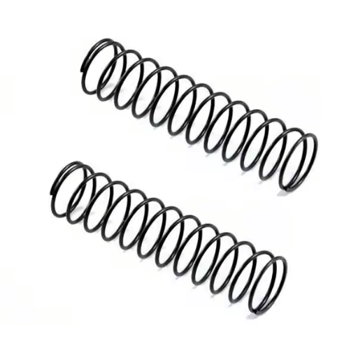
In the context of a compression spring, spring length is defined as the distance between the two ends of the spring in its axial line. This length changes according to the following three states:
Free Length: The state in which no load is applied to the spring and the spring is not compressed.
Compressed Length: The length of the spring when it is fully compressed and all the coils are touching.
Installed Length: The length of the spring with a specific working load being applied to it in the course of its application.
Free length is usually provided in the design; however, the other two lengths depend on the working load and spring rate.
A number of compression spring loaded length problems occur, and these are extremely important for proper functionality under defined conditions. A few of these factors are given below:
Free Length (L₀): 50 mm
Spring Rate (k): 10 N/mm
Applied Load (F): 100 N
The deflection (\( \Delta L \)) can be calculated as:
\[ \Delta L = \frac{F}{k}= \frac{100 \, \text{N}}{10 \, \text{N/mm}} = 10 \, \text{mm} \]
Resulting loaded length (\( L \)) is calculated as:
\[ L= L₀-\Delta L= 50\, \text{mm}-10\, \text{mm}= 40\, \text{mm} \]
This indicates the correct relationship between load, spring rate, and its effect on the spring’s length.
One of the most important parameters that determine the mechanical properties of a spring, such as its stiffness, deflection, and load bearing capacity, is wire diameter. In general, the stiffness of a spring (spring rate, \( k \)) is higher for thicker wires and thus, thicker wires will make springs less deformable under a given load. However, in the case of thinner wires, the spring rate will be lower and deflection will be larger for the same load. The relationship is defined by the material’s modulus of rigidity, the coil diameter of the spring, and the diameter of the wire — these are known parameters and basic equations of spring design. An engineer is challenged with choosing an adequate value of wire diameter to fulfill predetermined performance criteria along with material strength, fatigue resistance, and size limitations.
The spring rate or spring constant is computed using the following equation: k = F / x
The following explains each component.
k is the spring rate (force per unit of displacement).
F is the force applied.
x is the change in position or compression(length change).
For custom springs, factors such as material features, wire thickness, diameter of the spring, and number of coils will define the spring rate. These parameters are fed into complex equations so that the final design can fulfill certain predetermined values.
Step 1: Identify the Applied Force (F). Look up the force that is being applied to the spring and note it down. Express it globally either in Newtons (N) or pounds-force (lbf). For instance, if a weight of 50 N is applied, then F = 50 N.
Step 2: Record the Change in Length (x). Take note of how much the spring’s length has changed after the force has been applied based on the change you measured. This is done either in meters (m) or inches (in). For example, if the initial length of the spring was 0.3 m, and the spring extends to 0.35 m while the force is applied, then x=0.05 m.
Calculate the Spring Rate (k): To calculate the spring rate k, use the equation k = F/x. Using the sample numbers from the example problem:
\( k = 50N / 0.05m \)
\( k = 1000N/m \)
Verify Units and Accuracy: Ensure that all measurements and results reflect the same unit type (for instance, N/m or lbf/in) for the case of each calculation step to avoid making computation mistakes. Any variances which are considered experimental or any inaccuracies associated with taken measurements ought to be made via design tolerance inaccuracy bounds.
Analyze and Record: Using the calculated spring rate, determine if it meets the spring design specifications. If the spring rate value does not meet the expected performance, consider changing design parameters like the coil thickness, number of coils, or even the material type used to manufacture the spring.
The force required in spring design is essential to guarantee proper spring functionality. This determines how the spring is expected to behave under force application regarding load, compression, extension, or torsion. Calculating these forces accurately ensures that the spring is within the desired performance range, has minimum required wear, and does not failure prematurely.
The length of a spring is reduced as a compressive force is applied, relative to the spring constant (stiffness coefficient), \(k\). Hooke’s Law states that the force (\(F\)) applied to the spring will dictate the displacement (\(x\)) the spring will undergo, as shown in this formula:
F = k \cdot x
\(F\) = Applied force (measured in Newtons, N)
\(k\) = Spring constant (measured in N/m)
\(x\) = Displacement or change in length (measured in meters, m)
To illustrate, let’s say a spring has a spring constant of \(k = 200 \, N/m\). The displacement for an applied force of \(50 \, N\) can be solved as follows:
x = \frac{F}{k} = \frac{50}{200} = 0.25 \, m
This indicates the spring will contract by \(0.25 \, m\) under the specified load. With these values, designers can calculate how the spring will react under certain conditions and use this information to achieve proper functionality and safety limits within the operational range.
In analyzing the consequences of force applied on spring compression, it is pertinent to discuss the elastic limit of the spring in conjunction with Hooke’s Law. In excess of this limit, the material may experience some form of plastic deformation which makes it impossible for the spring to revert to its original shape after the force has been removed. Moreover, the prolonged use of the material may lead to changes in the spring constant \(k\) due to material fatigue which would consequently change the expected compression or extension. These considerations are necessary in the design of a system for its safety and functionality.
In order to determine the change in length (\(\Delta x\)) of a spring contracts under a compressive force, it is necessary to employ Hooke’s law. The law can be written as follows:
\[\Delta x = \frac{F}{k}\]
\(F\) refers to the force that is being used (\(N\) or newtons)
\(k\) is the spring constant (\(N/m\) newtons per meter)
\(\Delta x\) is the change in length of spring(m)
When adjusted, the equation reveals the change in length as follows: \Delta x = \frac{F}{k} This formula assumes the applied force remains within the elastic limit of the spring to avoid causing any deformation beyond recovery. For precise outcomes in engineering and system design, correct assessment of the spring constant and the force being applied is mandatory.
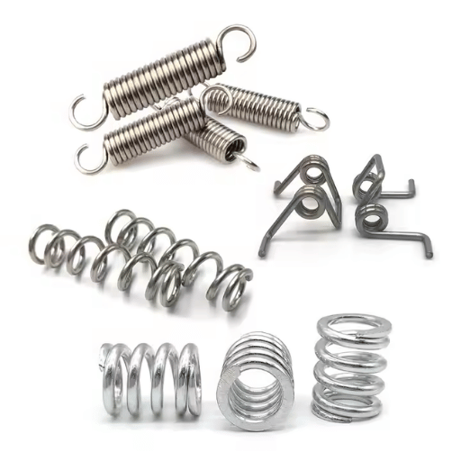
The primary purpose of extension springs is to absorb and store energy through a pulling force. Their operation is based on tension, and items such as hooks or loops are located at the ends to enable connection. Stretching extension springs, unlike torsion springs, increases their length, which makes them suitable for use in systems with controlled stretching, like garage doors, trampolines, and cars. In dynamic systems, these springs are preloaded to maintain robust initial tension and tight coil springs, which is crucial for their functionality.
To ensure proper performance of extension springs for their application, a number of specifications are defined. These include:
Wire Diameter – Ranges from 0.15 mm to over 6 mm based on load or application use.
Spring Rate (k) – Refers to the force exerted on the spring per unit of stretch (N/mm or lb/in), indicating the strength extending the spring by preset limits.
Maximum Load Capacity – The highest possible load a spring can endure without changing shape or getting damaged.
Free Length – Combination of any hoops or loops and the full length of the spring when in an uncompressed position.
Coil Count: Describes active coils that set the flexibility ratio and the amount of force the spring can handle.
Material Composition: Covers materials selection like stainless steel, carbon steel, and high-temperature alloys which are chosen depending on required resistance against wear and tear, corrosion, and temperature of the working environment.
Reliability also incorporates other performance parameters like fatigue resistance, as well as durability in repeated cycles and elongation. For example, a common extension spring in a garage door mechanism has a spring rate of 100 N/mm and a load capacity of 500 N. It is made of high carbon steel to improve service life. This engineering guarantees the springs will function for a long time under normal use.
The differences in energy storage and release between torsion and extension springs accounts for the difference in their spring rates. While torsion springs apply torque or rotary force that is directly proportional to the angle of twist measured in Nm/degree or Nm/radian, extension springs create force that also is directly proportional to distance but moves in a linear fashion, measured in N/mm. Each type of spring has a rate which is dependent on several means including, material properties, coil diameter, and the number of active coils. However, the primary differrence in spring type is in the method of force application: rotational in the instance of torsion springs and linear for extension springs.
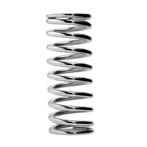
In a conical spring design, it is important to keep in mind certain relevant aspects for a multitude of aspects that influence the effectiveness of the spring. The following parameters are relevant to what the design could look like:
The spring index indicates the ratio between the mean coil diameter (D) and the wire diameter (d). It has considerable importance in regard to the shape and performance of the spring after it is manufactured. The ideal value of 4 to 12 is recommended to allow for ease of manufacturability, while maintaining performance.
Example Data:
Mean Coil Diameter (D) = 20 mm, Wire Diameter (d) = 2 mm.
Spring Index (C) = D/d = 20/2 = 10 distinctively shows in the example that the required spring index set for proper manufacturability is achieved.
This allows for tapered conical springs to be manufactured with the end coils having different diameters. The conical spring’s taper ratio has to be taken into consideration when determining the spring profile.
Example Data for Taper Ratio:
Large End Diameter= 30 mm, Small End Diameter= 10mm.
Taper Ratio = Taper Ratio = Large Diameter / Small Diameter = 30 mm / 10 mm = 3.
The load a conical spring is able to support and its corresponding defection is dependent on the strand’s material modulus of elasticity as well as the spring geometry. The narrowing coils compress sequentially so as to avoid buckling and obtain progressive stiffness.
Example Data For Load/Deflection:
Target Load (F) = 100 N, Expected Deflection (Δx) = 10 mm.
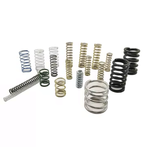
Material selection influences the durability, fatigue resistance, and maximum operational load of the spring. Depending on the application need and the environmental factors, high carbon steel, stainless steel, and special alloys like phosphor bronze are the most popular choices.
Example Material Properties (Stainless Steel 304):
Yield Strength 520 MPa, Modulus of Elasticity 193 GPa.
With this reference information along with precise calculations, conical springs can be designed to meet specific spatial as well as mechanical configurations while ensuring the desired performance for a variety of uses.
The spring rate for a spring is represented by the letter “k,” which refers to the deflection of such spring due to a given spring load that is generally regarded as the force required to be applied. The conical spring has a unique shaped coil that alters throughout its’ compression which makes the spring rate vary during its application. A conical spring’s spring rate can be calculated with the following formula:
Spring Rate (k):
\[ k = \frac{Gd^4}{8N D_m^3} \]
\( G \): Shear modulus of the provided material. (Pa)
\( d \): The standard wire diameter (m)
\( N \): Total number of active coils.
\( D_m \): Mean value of coil diameter (m).
It is said that because of its geometry, conical spring does not have all coils active at a given time. To do this, it is best to apply an incremental technique that allows performing an analysis for the accommodating of the coils. Precise prediction of the spring behavior under load may be done with modern finite element analysis software. Such theoretical calculations can alternatively be verified through empirical testing dependent on the specific conditions of application.
In particular, if one uses a stainless steel spring (like Stainless Steel 304) with the described material properties, and also uses correct coil measurements, the spring rate can be designed to fit specific system parameters. This guarantees that the system operates as required while meeting design constraints in terms of stiffness and deflection limits.
Conical springs are employed for applications which require minimum space and offer variable spring rate. These include the automotive where they serve to optimize shock absorption in suspension systems and in electrical contacts where the spring serves to open and close a circuit when there are compressive forces present. Furthermore, they are incorporated into industrial machinery to permit lower material use while dealing with different load situations. Their special construction allows flexibility and durability, which makes these systems caters for compact systems.

A: Understanding the concepts of solid height and free length is imperative in any height compression springs. Neutral furnace–compressed free length is the spring’s length when it is in its unloaded position. This is significant because it aids in determining the amount of travel compression is needed to place the spring in the desired position.
A: In calculating spring force, a number of parameters such as wire diameter of the outer and mean diameter of the coil and the number of coils have to be taken into account. As outlined in Hooke’s Law springs also have restoring force which is constant to the amount of displacement from the unloaded length of the spring.
A: Solid height (or solid length) refers to the height of a spring that is fully compressed, with no additional force capable of being applied to a torsion spring. Limits, such as solid height, should be observed to avoid ruining the spring, and at the same time, assist in ensuring the spring functions within its limits in terms length and motion.
A: When moving a spring, consideration should be given to the following factors: spring force, mean diameter, free length, solid height, and the maximum travel with respect to solid height. With these factors properly calculated, the spring will operate without failure.
A: The mean diameter has a significant impact on the spring’s capacity to store and release energy. Load capacity and stiffness depend on the mean diameter the spring is designed for. If a mean diameter that is expected is used, the spring will perform its duty in the application.
A: Stock springs have been manufactured in advance so they may be ordered and used immediately, unlike custom springs which are made individually according to a specified design. Applications needing immediate solutions are best suited for stock springs, whereas specialized tasks are best done with custom springs.
A: In case of issues computing the right spring length, it would be best to reach out to us. We can help figure out the spring length specification and your application so that the spring you receive will be suitable for your needs.
1. Experimental Analysis of Transverse Stiffness Distribution of Helical Compression Springs
2. A Study on the Evaluation of the Compression Behavior of PLA Lattice Structures Manufactured by FDM
3. Investigation on Design and Fabrication of Continuous Fiber Reinforced Composite Helical Spring for Automobile Suspension

Manufacturing processes are quite complex, and the choice of a production method is directly related
Learn More →
There are two major manufacturing methods for producing plastic prototypes that most people find useful
Learn More →
As a person involved or interested in the design and production of plastic components, it
Learn More →