
Manufacturing processes are quite complex, and the choice of a production method is directly related
Learn More →
Tools such as the fly cutter tool are handy for both machinists and engineers. They assist in accomplishing accuracy and productivity in diverse milling operations, including crafting extensive flat surfaces and even achieving polished finishes. It is hard to think of any other tool that can match the versatility offered by this one. How does it function, though, and what is the reason for it being such an integral piece of modern milling machines? Besides the working mechanics, you will also learn the primary applications and the dos and don’ts of the fly-cutting tool. All insights provided will help you optimize its application to achieve the best results while understanding its significance in the machining procedure. In this article, we will outline how to make the most out of this essential tool and influence your milling capabilities.
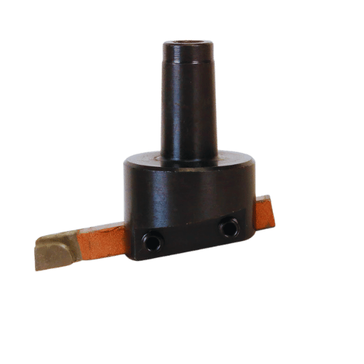
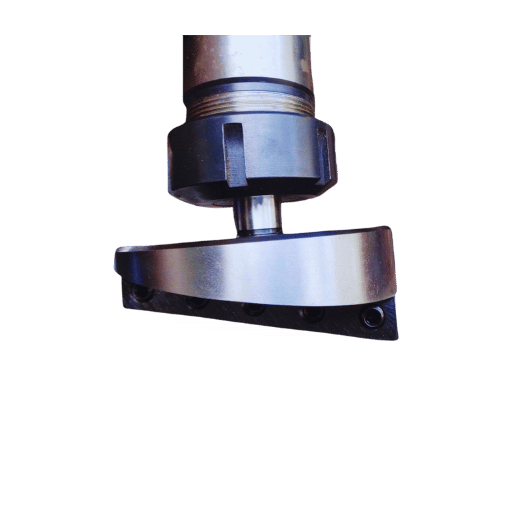
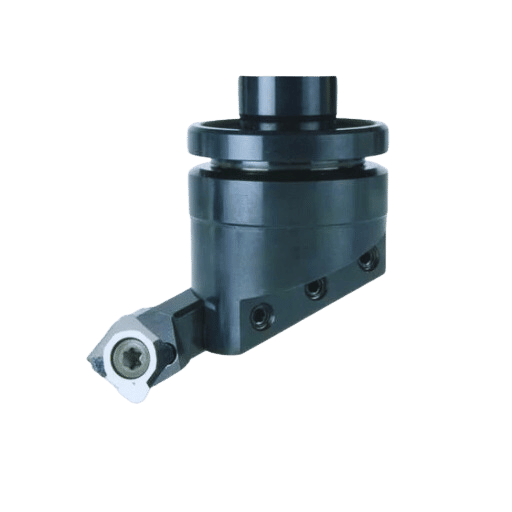
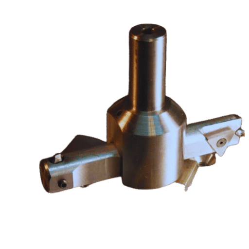
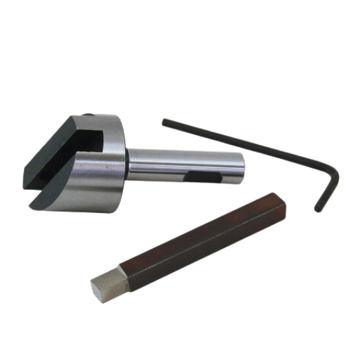
A fly cutter is considered a single-point cutting tool used for making flat surfaces in milling machines. It consists of a body that carries a tool, typically made of high-speed steel or carbide, which rotates to cut the workpiece in the machine. Unlike multi-point cutting tools, the fly cutter employs a single cutting edge which makes it suitable for producing high surface finishes over large surfaces in different forms of milling. It functions by removing an amount of material as the edge of the cutter passes over the workpiece. The simplicity of an economical tool makes it versatile for different milling processes.
A single-point cutting tool is fixed at the periphery of a rotating spindle and the surface of the workpiece is translated beneath it. The surfaces are cut in an arc, sweeping motion which guarantees a constant surface finish. It has a very low configuration which allows for effective coverage of large flat surfaces economically, which is why it is widely used for operations that require accuracy and cost efficiency in the manufacturing sector for milling work.
A Fly-cutter Tool is comprised of several basic parts that work in combination to efficiently and accurately remove material from components:
Cutting Tool
The cutting tool is typically a single-point HSS or carbide-tipped cutter. It is bolted at a predetermined position and angle that defines the quality of the resulting cut. Sometimes, advanced materials such as polycrystalline diamond (PCD) and cubic boron nitride (CBN) are used to machine harsher materials. These materials provide increased life and cutting effectiveness for the manufacturing industries.
Spindle
The spindle is the axis of rotation for the fly cutter and drives the cutting tool. Fly cutters are bolt-to-milling machine spindles that have high rigidity to reduce the cutting vibration and improve the machining accuracy. To satisfy different materials or cutting depths, spindles have variable speeds.
Tool Holder
The arms of the tool holder are adjustable to the pole of the fly cutter to aid in securing the cutting tool. The tool holder performs the function of a tool clamp and the supporting arms are designed to provide stability throughout tool operation. These features design the tool holder.
Counterweight
Counters are fitted to fly cutters to smooth the operation of the machine and consequently reduce the amount of vibration encountered. With this type of construction, balance is provided, particularly at increased spindle speeds.
Body
The body is largely composed of durable materials such as hardened Steel or aluminum alloys.” It holds all other parts of the machine and transfers the loads caused during the process of cutting. The stiffness of the body helps to ensure accuracy and increase the life of the tool.
Fastener
Screws and bolts that are classified as fasteners, fix the cutting tool and other components to the body of the machine. These fasteners should be fixed at certain torque values so as not to lose precision and safety to the machine.
Specification and Technical Data
Cutting Diameter
Depending on the machine’s capabilities and requirements of the application, fly cutters have cutting diameters that can range from small, below 4 inches, to over 12 inches.
Cutting Speed and Feed Rates
The average cutting speed is from 30 to 100 meters per minute, and the feed rate, which is usually lower than normal due to the surface finish and type of material, is often measured in millimeters per revolution (mm/rev). In precision milling, the quality of the surface is better when the feed rate is slower.
Material Compatibility
Why Fly cutters are designed for numerous materials such as Mild steel, aluminum, softer alloys, cast iron, etc. By choosing the proper cutting tool material, a guarantee is made that the optimum performance based on the hardness of the workpiece is achieved.
The effectiveness of a fly-cutting tool is determined by the selection and combination of its components, alongside the proper machining parameters for the specific material and application.
Employing a fly cutter with a milling machine has its own distinct steps which, if performed accurately, will ensure efficient material removal and precise machining. The steps employed are discussed below:
Selection of the Fly Cutter
Pick a fly cutter that will best suit the material that needs machining. Softer materials such as aluminum can often be machined using high-speed steel (HSS) tools. However, as materials become harder, for example, with stainless steel, the use of carbide-tipped cutters would become necessary. Additionally, the surface finish and cutting area of the desired workpiece must be considered when selecting the diameter of the fly cutter.
Setting up the Workpiece for different types of milling
The workpiece must be clamped or placed in a vise to the milling machine table securely. It is critical that the workpiece is flat and level so that cuts that are taken do not lead to vibrations or unevenness. While machining tolerances tend to differ, a fly tool can help achieve tolerances for flatness which can range anywhere from 0.0005 to 0.001 inches, however, this will depend on the machine’s capabilities and tolerance levels.
Installing the Fly Cutter
Fit the fly cutter into the milling machine spindle and tighten it securely. Runout should also be checked so that the cutter does not misalignment during movements. An imbalanced fly cutter can result in chatter that reduces surface quality so ensuring alignment and balancing with the minimal amount of runout is preferred.
Setting Cutting Parameters
Select the spindle speed, feed rate, and depth of cut for the job. These variables are determined by the material being machined as well as the specification of the tool. For instance, when fly-cutting aluminum, it is usual to use spindle speeds between 1,500 and 3,000 RPM with a feed rate of 4 to 10 inches per minute. With harder materials such as steel, slower speeds, and feed rates are sometimes necessary to limit wear on the tool.
Performing the Cut
To begin, start the milling machine and lower the fly cutter to the workpiece while making light passes. Deep cuts in a single pass should be avoided prior to the surface finish as tool wear and surface finish can become worse. Aim for a depth of cut between 0.005 to 0.020 inches per pass to get the best results.
Monitoring the Process is essential for optimal tool-cutting performance. Observe the machining operation from beginning to end to ensure it is done correctly with tool cutting. Check for tool chatter, cuts that are not uniform, and overheating of the tool(s) as these may require adjustment of the spindle speed or feed rate. Use cutting fluids as these tend to work better for harder metals and reduce friction improving surface finish quality when machining.
Final Examination
When the machining operation is finished, check the surface finish and dimensions of the workpiece for accuracy. Depending on the material and the way the process is set up, fly cutting can provide an exceptionally smooth finish and a Ra value of 16 microinches or lower.
A milling machine can provide accuracy and quality in machining when used properly with a fly cutter. Proper setup, tool maintenance, and optimizing working parameters are essential to maximize productivity and prolong tool life.
While both fly cutters and face mills can be used to produce flat surfaces, they differ structurally, operationally, and in their intended uses. Fly cutters are single-point cutters that utilize an arm for rotation which translates to cheaper and more multifunctional machining. Fewer components typically translate to lower expenditure on tooling as well as increased ease of regrinding the cutter. Fly cutters work well when light material removal and very smooth surface finishes are necessary. These are often not critical needs, but rather aesthetic ones.
In contrast, face mills employ multiple cutting inserts which are fastened onto a larger diameter tool body. The multi-insert configuration provides higher-efficiency face mills with the capability to remove greater volumes of material in a single pass at higher feeds and speeds. Such capabilities are certainly advantageous in mass production procedures or difficult processes. Additionally, face mills outperform fly cutters when dealing with tougher materials or larger workpiece surfaces. The multiple blades share the cutting force, decreasing wear on the tool, therefore, a face mill can reach cutting velocities of over 500 surface feet per minute (SFM) and will have several times higher metal removal rates (MRR) than a fly cutter depending on the machine and material.
Moreover, face mills tend to utilize more sophisticated insert geometries and coatings, like PVD-coated carbide or ceramics, which improve their wear resistance and enhance their machinability on hard materials like stainless steel and titanium. Yet, the accuracy and meticulous detail needed to recondition or replace the tool inserts may result in higher costs than the simpler maintenance fly cutters require.
When both tools are compared, a decision must be made in which the relevant factors are tolerances, surface finishes, materials, and the volume of production. Face mills offer maximum productivity and material removal efficiency whereas fly cutters provide more economical tooling and better surface finish.
Fly cutters are beneficial when finishing wide, flat areas and are commonly used in low-volume machining precisely because of their cost efficiency. They work best on softer materials and in situations where little cutting force is needed.
In contrast, end mills serve better in contouring, slotting, or pocketing operations. They work well in high-speed applications and are effective against harder metals, thus making them suitable for most materials. In addition, end mills are the best choice for tighter tolerance and complex geometry features.
The choice between end mills and fly cutters comes down to the particular processing operation, the workpiece material, and the finishing requirements.
The benefits of fly cutters in machining processes provide solutions for specific problems:
Fly Cutters Are More Cost Efficient
As compared to end mills, fly cutters are more affordable. Their design features either a detachable tool insert or a single-edged cutting tool, which decreases the frequency of tool changes and cuts down on operational costs.
Fly Cutters Have Quality Surface Finish
Fly cutters provide surface finishes for large flat areas that need smoothness due to their sweeping cutting motion alongside a single-point cutting edge. Therefore, they are better suited for areas that need a high degree of smoothness and uniformity.
Fly Cutters Are Effective On Large Areas
Among other tools, fly cutters are masters in machining broadened surfaces. They take fewer passes to cover larger areas than end mills and other tools, leading to a reduction in the time needed for machining large components.
Fly Cutters Provide More Options For Insert Selection
Fly cutters are interchangeable with cutting inserts, providing adaptability to different materials. They can be used with carbide, high speed steel, or diamond-tipped inserts for soft metals, hard metals, or composites enabling versatility with different materials.
Easiest Set-Up Tools
Setting up a fly cutter, particularly one with an inch head, is relatively easy. The single-edge knives are slightly easier to put in place and maintain as compared to multi-flute tools which are cumbersome to deal with.
Lower Heat Buildup
With their larger cutting arc and slower cutting speed, fly cutters do less work and therefore do not heat up as fast. This helps minimize the chances of thermal deformation, especially for materials that are sensitive to heat like aluminum and plastics.
Longer Tool Life
The useable life of fly cutters is generally longer than other tools due to the slower cutting speed and use of durable inserts which results in lower wear rates. The increased tool life results in decreased costs over time for manufacturing operations.
Taking all of these aspects into account, a manufacturer would know what areas to use fly cutters with the hopes of decreasing costs while achieving an efficient and high-standard machining output.
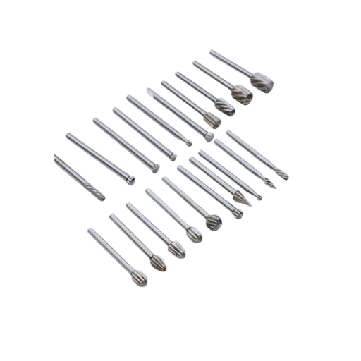
HSS Bits
HSS seems a bit out of place, it should have been highlighted in one of the preceding phrases. Make sure to say that you work with HSS bits (rather than, you work with HSS bits, which is ever so slightly off-key). HSS bits cutting softer materials like aluminum and mild steel can be done with a fair amount of toughness and additionally reasonable wear ZResistance (which seems a bit childish, change it up). Furthermore, HSS bits are very adaptable, which is nice.
Carbide Tipped Bits
Precision machining can be complex and daunting to most, which is exactly why these bits are ideal. Carbide-tipped bits have longer tool lives and an increased ability to handle harder materials, all while maintaining impeccable cutting performance (think stainless steel).
Cobalt Steel Bits
Reshape this section with even greater difficulty, HSS bits are easier in comparison to cobalt steel. Cobalt steel bits increase withstanding heat and maintain impeccable durability making them well suited for intense cutting of stainless steel and titanium alongside other materials so tedious to work with.
Diamond Coated Bits
Like nonmetallic materials, ceramics, or composites these diamond-coated bits have excelled in wear resistance (i.e. increase the level of difficulty for these two paragraphs). They work great in dealing with harder surfaces like PCBs (yeah, expand acronyms) or just about anything else that requires machining.
These words make clear that bit selection should be made carefully taking into account the material, finish, and operational methods that optimize the desired performance output and efficiency.
Cutting tools are made from two popular materials, Carbide and High-Speed Steel (HSS), both having their unique advantages when it comes to different machining applications.
1. One of the most important elements while machining using the best tools is to consider hardness along with resistance to wearing down over time.
Carbide tools are a lot more rigid compared to HSS and can take a higher beating in ranges around 70 HRC (Rockwell Hardness) and HSS measure in at 62 to 64 HRC. The tools will also be enabled to fight problems such as tool life along with wear resistance which is dependable on the amount of abrasive composites being machined with like materials or cast iron.
2. Productivity and Speeds Rotating Tools
Compared to HSS tools, carbide tools are able to work at way more efficient cutting speeds. HSS tools being effective only in a range of 20 to 30 meters per minute are easily outrun by the over one hundred meters per minute that depending on the material, carbide tools are capable of. This increase in speed has a direct correlation with productivity, machining time efficiency, and overall effectiveness for high-volume/precision operations.
3. Heat Resistance
Carbide-cutting tools are suitable for machining operations with high heat of machining due to their high melting point, thermal stability, and resistance to softening. They can maintain their hardness at temperatures up to 800-1000°F, making them suitable for heavy-duty and high-speed cutting. In contrast, HSS tools tend to soften at higher temperatures, becoming less useful at around 600°F.
4. Cost Efficiency
Although initially more expensive than HSS, the longer life and increased efficiency of carbide tools often offset the cost over time. This makes them ideal in production environments that require cost-per-item and quality control. HSS tools, however, are less costly and are suitable for more general, low-volume machining.
5. Versatility and Toughness
With their superior toughness and resistance to chipping, HSS tools are more useful for manual machining or interrupted cuts, making them more versatile. Carbide tools are more brittle and susceptible to fractures and structural failure from heavy impacts and uneven load.
Comparative Table of Key Characteristics:
|
Property |
Carbide |
High-Speed Steel (HSS) |
|---|---|---|
|
Hardness |
~70 HRC |
~62-64 HRC |
|
Cutting Speed |
Up to 100+ m/min |
20–30 m/min |
|
Heat Resistance |
~800–1,000°F |
~600°F |
|
Cost |
Higher initial cost |
Lower initial cost |
|
Toughness |
Lower |
Higher |
|
Suitable Applications |
High-speed, precision |
General-purpose, impact-prone |
By understanding these advantages and limitations, manufacturers can select the most appropriate tool material based on the specific demands of a project, balancing factors such as cost, wear resistance, cutting speed, and toughness for optimal results.
To choose the optimal tool bit for your workpiece, I consider the project-specific details. For example, when the requirements are accurate and high cutting speeds, I go for carbide as it is extremely hard and heat resistant. Yet, for tasks involving impact and more general-purpose machining, I utilize high-speed steel (HSS) due to its toughness and more affordable price. By analyzing the tool material’s cost-effectiveness along with the required toughness, cutting speed, and heat resistance, I make certain to meet the demands of the workpiece to ensure optimal performance.
Owing to their effectiveness and straightforward design, fly cutters have found a wide range of applications in machining operations. They are one of the primary tools employed when surfacing large, flat regions on metals such as aluminum, steel, and cast iron. Fly cutters are often used in the aerospace, automotive, and tooling sectors that require high-quality finishes on workpieces due to the broad cutting paths of these tools.
Fly cutters can also be used on softer materials like composites or plastics that require clean surfaces. In low-production scenarios, or when working on prototypes where economically viable insert or specialized tools cannot be used, fly cutters are ideal. Due to the adjustability of these tools, many machinists prefer fly cutters because the diameter of the cutting path can be altered, which ensures maximum productivity.
Recent tests conducted for modern machining tasks provide evidence to support the claims regarding the efficacy of fly cutters. With fly cutters, the average surface roughness values when processing aluminum rests on 0.4 µm Ra, which certainly beats the value achieved using CNC router heads. Coupled with the fact that these tools work well at lower spindle speeds and operate with limited machine power, it is clear that fly cutters are a great economical solution in low-budget setups.
Several factors which include tool geometry, material properties, cutting parameters, and machine stability need to be taken into consideration for achieving a high-quality surface finish with salient factors of fly cutting. While these variables are altered, machinists can smoothen and sharpen surfaces in aluminum, brass, and selected grades of steel or composite materials with precision. This optimization takes the skills of a considerable specialist.
Tool Geometry and Material Selection
As with other applications, cutting tool selection has a greater influence on surface quality. Fly cutting sophisticated materials like aluminum and brass is enhanced exceptionally fast with the use of sharp, high-quality single-point cutters made of durable materials such as carbide, polycrystalline diamond (PCD) tools, or even cheaper quadrangular inserts as long as edges are well-ground. The use of well-designed tools with proper rake angles and edge preparation enables smaller cutting forces which causes lower amplitude of vibrations that cause surface roughness.
Cutting Speeds and Feed Rates
For achieving uniform surface finishes, optimizing the cutting speed which is measured in surface feet per minute (SFM), and feed rate which is measured in inches per minute (IPM) becomes optimally crucial. Studies have shown that for roughness values below 0.5 micrometers for aluminum surfaces, it is sometimes necessary to set the tool cutting speeds ranging from 600 to 1000 SFM for low feed rates of less than 0.004 inches per revolution per tool. These settings minimize tool marks while keeping chip thickness steady.
Spindle Stability and Vibration Control
While using fly cutters, machine rigidity as well as spindle stability must be maintained. Minor vibrations can create chatter marks that spoil the finish. Balancing the fly cutter head is one of the most important processes. Surface uniformity has been shown to improve even more with the use of advanced high-speed machinery centers with vibration-damping devices. These machines have shown improved surface uniformity because of their ability to reduce vibration.
Coolant and Lubrication
Effective application of coolant or cutting fluid helps in achieving a finer surface finish and increases tool life. Coolants reduce workpiece temperature, preventing heat expansion. A water-soluble coolant applied through a misting system usually meets the cooling needs of the workpiece when it is aluminum.
Measurement and Quality Control
The development of new tools for surface metrology, including profilometers as well as optical scanners, has made it easy to assess surface roughness. Such devices enable feedback to confirm that set machining tolerances are achieved. Fly cutting has reached an impressive level of 0.4 µm Ra surface roughness levels. That is the roughness level that can be achieved with minimal effort during ideal conditions. The process’s competitiveness for industries such as aerospace, medical, and optics manufacturing that require fine finishes is because of the capability of fly cutting to reach ideal surface roughness levels.
If properly controlled, fly cutting offers superior surface finishes like none other, while also being cost-effective and less labor-intensive than all other machining techniques.
Ensure the Workpiece is in Place
Make sure the workpiece is rigidly fastened to the milling table so that there is no movement during the operation. A vise or clamps according to the material and size of the workpiece should be utilized.
Align the Fly Cutter
Attach the fly cutter, and loosely plug it into the spindle so that the cutter can be moved with a lot of resistance to its rotatory motion. Confirm the cutting tool is at the center and the process of inventing a new tool around it is not causing vibrations or being cut out quite well.
Set the Cutting Depth
Set the cutting tool to the desired depth of the cut. Take a light-cut surface to avoid wearing out the tool or damaging the surface too much.
Check Tool Feed Rate and Revolutions
The spindle RPMs and the distance the cutter moves into the workpiece should be preset from the operator’s periphery of the machine. As always, check the manufacturer’s suggestions to ensure that the parameters allow for the best output result.
Check the Surface Finish Tooling
Ensure the edge is not damaged, chipped, or less sharp. These conditions are bad for the surface finish and cause overheating, which is something nobody wants.
Make Test Pass
Run a test pass on simulation material to check the settings of the machine, the machining part’s stage, and any further parameters. Make any revisions that seem appropriate before you attempt to machine the part.
With strict adherence to every procedural detail, the fly cutter will operate effectively and produce high-quality surface finishes.
Follow Proper Personal Protective Equipment (PPE) Guidelines
Always wear safety glasses and goggles to shield the eyes from flying particles. Furthermore, while working on heavy-duty machines, hearing protectors, gloves, and anti-skid shoes are also required.
Clamp the Machined Parts Correctly
Always confirm that the workpiece is properly clamped to eliminate any possibility of it shifting during the machining process. A workpiece that is not securely clamped can result in damage to the cutting tool or injury due to excess vibration or improper cutting.
Maintain Safe Speeds
Axis fly cutting entails the use of heavy forces on the cutting tool and the spindle. Operating above or below the recommended or ideal speed range can result in excessive wear or breakage. For instance, for large-diameter fly cutters, a speed of below 2500 RPM is ideal. This speed also promotes safety and gives the best results.
Avoid Coming in Contact with Moving Parts
With the spindle and fly cutter in motion, always keep your hands at a safe distance away from the machine. You should never use your hands when getting rid of chips. Instead, use a vacuum or brush.
Examine Parts of the Machine from Time to Time
Routine examination of the parts such as the spindle and of the clamps and notches which hold the pieces that are mounted on the head, assist you to see if there is any possibility of wear or misalignment which could be dangerous. Note that worn parts should be replaced immediately to avoid operational risks.
Ensure Sufficient Chip Clearance
Fly cutting generates a significant volume of chips that, if not removed, can interfere with the process or damage the tool. Employ efficient coolant systems or air blasts to keep the cutting area free from obstructions.
Control Thermal Accumulation
Intensive cutting action will produce heat on the tool and workpiece. Employ cutting fluid when necessary to aid in the dispersion of heat, extending tool life as well as preventing any thermally induced expansion from impacting accuracy.
Following these specific safety procedures allows the operators to minimize all possible dangers while maximizing the efficiency and effectiveness of fly-cutting processes.
Balancing tool efficiency and workpiece quality entails achieving the optimal cutting speed and feed rate. The cutting speed, as it pertains to the operation and the corresponding material, has to be executed as efficiently as possible for material separation with minimum and optimal tool wear. Meanwhile, the feed rate level should be enough to keep the cutting action ongoing without generating chatter or rough surfaces. Seek advice from the manufacturer’s documentation because both are set specific to the tool and material combination. Adjusting these parameters is beneficial because it improves accuracy and precision, enhances tool life, and lowers the overall operating cost.
A: A fly-cutting tool is used on milling machines to generate flat surfaces. For this reason, a fly cutter is classified under the cutter types of milling. A fly cutter, which is invariably employed on CNC milling machines, is more efficient than conventional fly-cutting techniques.
A: In contrast with other milling cutters which employ numerous cutting edges, a fly cutter only uses one or occasionally two tool bits. Such configuration enables the edge to move in a circular motion as it cuts into the workpiece, therefore making the milling of flat surfaces simpler and easier.
A: Compared with fly cutters that incorporate a single tool bit, those that have two tool bits are more advantageous as they result in higher material removal rates and better surface finish. They enable higher productivity than other forms of fly-cutting processes.
A: Tool bits for fly cutters are made most commonly from high-speed steel or carbide. For rough cutting, carbide tools have greater durability, can maintain sharp cutting edges longer, and are more optimal for extending tool life, making them the preferred choice.
A: The available sizes for fly cutters are numerous. They are usually measured in the diameter of the cutting head and shank. Common cutting head dimensions include mm for diameter, while inch is used for shank sizes to fit various machine tools.
A: The fly cutter is attached to the milling machine by inserting and locking the shank into the spindle of the machine. The setup might be different for various machines, but usually involves the use of tightening a drawbar or tool holder such that the cutter is gripping.
A: Absolutely, CNC machines use fly cutters routinely. They are extremely useful for cutting flat surfaces since they work faster and give a smoother finish compared to traditional milling techniques.
A: Examples of fly cutters include single-tool bit and double-tool bit types. These categories reflect the varying surface finish and rate of material removal that may be encountered. Different machine shops apply these tools depending on their project needs and the type of material they’re cutting.
A: Concerning the specific machine that is to be worked on, there are several things to consider such as the material to be worked on, surface finish, the size of the milling machine, and if its productivity needs to be improved. Also very important are the cutter’s rotary motion, the rake angle, and the kind of milling processed (CNC or manual).
1. Title: “Smart Cutting Tool Incorporating a Surface Acoustic Wave Sensor With Application to the Fly-Cutting Process”
Notable Results:
Research Approach:
2. Title: “Tool path modeling and fabrication of multi-boundary lens array by tool offset end-fly-cutting”
Major Insights:
Research Methods:
3. Title: “Ultra-Precision Fly Cutting Machine Tool Dynamics – Hybrid Multibody System Method”
Significant Outcomes:
Research Approach:
Manufacturing processes are quite complex, and the choice of a production method is directly related
Learn More →
There are two major manufacturing methods for producing plastic prototypes that most people find useful
Learn More →
As a person involved or interested in the design and production of plastic components, it
Learn More →