

Manufacturing processes are quite complex, and the choice of a production method is directly related
Learn More →
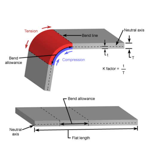
Accomplishing accuracy in sheet metal bending is a fundamental form of metalworking that has a significant bearing on the quality and use of the finished product. An important factor in this process is the bend radius which affects the material’s integrity, the strength of the structure, and the overall accuracy of the design especially concerning the internal bending radius. Whether a professional or a novice, knowing the minimum bend radius for different parameters is important in the design of parts and assembly of structures. This guide delves into the concepts of a sheet metal bend radius, discussing its significance, its physics, and how to achieve it with precision. By the end, you’ll understand the basics of optimizing your bending methods to guarantee successful outcomes on every occasion.
The radius of a bend on a piece of sheet metal is referred to as the sheet metal bend radius. It is critical in manufacturing automation since it influences the strength, look, and usability of the final product. If the bend radius is used correctly, cracking, material deformation, or structural weakness is unlikely to happen. It also guarantees that the part complies with design requirements and functions properly in its intended application. For achieving consistently high-quality results on metal work, maintaining proper bend radius is essential.
In the process of bending metal sheets, the bend radius is understood as the smallest radius that can be achieved by bending the metal without damaging it or making it prone to cracking or weakening. The bend radius is influenced by the type and thickness of metal, the way of bending it, and what result is expected. Meeting the suggested bend radius guarantees that the material loses it structural integrity and meets the design features which is why it is an important factor for consideration in accurate and fine fabrication work.
A finished part’s material properties and overall strength is greatly affected by the bend radius. Overly tight bend radiuses increase the chances of stress concentrations forming around the bend which could cause a material failure in the form of cracking or fracturing. To illustrate, 6061-T6 aluminum alloys are known to be sensitive to sharp bend radiuses which can result in exceeding elongation limits. As a general rule of thumb, standards say that ductile materials should have a minimum inner bend radius of at least one point five times the material thickness while less ductile metals could reach three times the thickness.
Additionally, unfavorable bend radius choices could also change the durability and functionality of the component due to thinning and material distortion around the bend. Research suggests that having a rounded bend radius can help ameliorate material deformation by evenly spreading the stress. For instance, steel holds greater tensile strength, and therefore performs better in load-bearing applications when it is bent at a radius equal to two times its thickness than a tighter radius.
The prediction of the stress concentration and the optimization of the bend radius for intricate contours is provided by advanced computer software, like finite element analysis (FEA). This allows the engineer to compute the effects of differing radii on the material and make design changes that follow the engineering criteria, as well as improve the service life of the components being manufactured.
The minimum bend radius significantly affects the structural soundness, accuracy, and feasibility of the production of any sheet metal part. Smaller bend radii tend to increase the chances of material deformation such as cracking and wrinkling. An example of this could be found in metals with low ductility, such as alloys of aluminum which are far more brittle than steel and thus need a larger bend radius to avoid breakage.
From a design standpoint, the radius of a bend affects the measurements and the overall angular precision of the particular piece. A predefined bend radius makes it possible to produce angles with uniformity, which is paramount for parts that require precision fit like in automotive and aerospace construction. Also, springback—the tendency of enhanced materials to revert to their original form—needs to be considered as it has a chance of making bends less accurate. Studies show that smaller radius bends have large springbacks that must be compensated for in design and manufacturing, especially in the case of tighter radius bends.
Practically, picking a suitable bend radius improves fatigue resistance and load capacity. Engineering calculations show that a larger bend radius reduces stress concentration along the bend line in a metal component, increasing the number of cycles the part can withstand. Larger radii, for instance, increase the longevity of sheet metal chassis used in heavy-duty machinery that faces cyclic loading.
A tighter radius also increases tooling costs as the metal needs to be bent with more force. Both the time spent producing the metal component and the operational costs are increased. Cost-effective optimal bend radius design needs to account for functional requirements as much as possible.
The minimum bend radius is greatly influenced by a material’s thickness and its type or composition. Generally, thicker materials are more resistant to deformation and, therefore, require larger bend radii. This happens because the material’s fibers on the inside of the bend get compressed while the ones on the outside are getting stretched. The thicker the material is, the more stress is experienced. Metals such as steel and aluminum, for example, when bent, have a target radius between 1-3 times the materials’ thickness, or else cracking and weakening are inevitable.
The type of material significantly impacts the minimum bend radius as well. Ductile metals like copper and aluminum allow for more flexibility than high-strength steel or titanium. It is for this reason softer metals can endure larger deformation while harder metals fracture. There are also industry guidelines, set by ASTIM and ISO, regarding suggested bend radii for specific materials. Annealed aluminum is estimated to require a bend radius ranging from 1 to 2 while high-grade steel needs a radius of around 2.5 to 3.
Other factors include the temper or heat treatment state of the material since hardened materials are usually less ductile and require larger bend radii. These properties, as well as the results from mechanical testing and actual operational needs, have to be taken into account by the manufacturers and designers to achieve the most favorable bends with minimal damage to the material.
Reference tables for bend radius are very useful platforms for engineers and manufacturers when dealing with sheet metal by providing an initial or starting point to calculate the minimum bend radii for different materials. These tables normally consider material type, thickness, and temper among other factors. For example, Aluminium alloys 5052-H32 suggest a minimum bend radius of 1 times the material thickness. In comparison, tougher and less ductile 6061-T6 alloys may need 2 to 3 times the bend radius to thickness ratio lest they crack.
Bend radius recommendations for cold rolled steels, for example, tend to be between 1 to 1.5 times the II/T ratio for different grades and tempers given the material’s ability to hold its structure outside of the bend. Much stronger and less ductile than carbon steel, stainless steel may need greater bend radii, usually ranging between 1.5 to 2.5 times II/T thickness ratio. In contrast, copper and brass are very ductile, needing minimum bend radii equal to or slightly higher than pliable materials’ thickness.
The selections are to be matched with the production methods that involve die type, tooling, bending angles, and other relevant parameters. Also, the application of a bend radius greater than the minimum radius specified in the tables is useful for durability enhancement by reducing residual stresses in the bent area, thus improving performance over time in harsh environments. Following this approach guarantees reliable and repeatable bends, which pass the structural and functional checks.
To estimate the minimum bend radius concerning material traits, some important tips are listed below.
As a general rule, for ductile metals, the minimum bend radius is equal to at least 1 times the material thickness and 2-3 times for the less ductile ones. To get accurate numbers, make sure to check the documentation from the manufacturer or engineering sources.

Such rules should be checked against the specific properties of a given material. It always makes sense to ask the supplier or standard sources within the market of the given industry.
In comparison to aluminum or mild steel, stainless steel is considerably stronger, which necessitates a larger bend radius. For stainless steel, a bend radius of 2 to 3 times the material thickness minimizes the chances of cracking. However, more malleable materials, like aluminum, generally have less stringent restrictions and can be bent with a radius of 1 to 2 times the material thickness. Ensure that you consult material-specific guidelines or supplier recommendations for optimal bending practices.
Uniformity, dependability, and safety are maintained in the final product by following industry standards in sheet metal design. In my personal experience, following these rules minimizes the chances of mistakes, limits the waste of materials, and assures suitability to the manufacturing processes. It also enhances the cooperation between the design and production departments because these standards set a minimum level of expectation and quality. This culminates in a simplified and more efficient production process while achieving quality standards more cost-effectively.
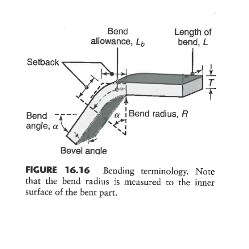
The radius of a bend influences both the flange length and the bend allowance of a sheet metal part. an increase in the bend radius would require additional material to be used to complete the bend, and that will consequently change the measurements of the bend allowance which is the material that is used in the bend’s curve. In the same way, flange length, which is the part that stretches from the edge to the bend, is impacted by the radius because a larger radius may change the flat layout dimension of the part. If all the factors earlier noted are controlled with the bend radius taken into account, the dimensions of the part would be accurate and would not get deformed or fail during the process of fabrication.
Students will review several strategies and processes that contribute to achieving balance among shape, function, manufacturability, and form in any sheet metal design. For example, one must consider the component’s and features’ purpose with its shape while also considering production efficiency. Other strategies include eliminating complex geometric shapes that are difficult to fabricate, using materials that meet required performance and manufacturability levels, and considering general tolerances along with fabrication possibilities. Collaboration with the manufacturing teams during the design stage is crucial to pinpoint possible difficulties at an early stage to ensure cost-effective production without sacrificing the design quality or functionality.
Follow Material Guidelines
Consult material specifications to establish the minimum bend radius of the selected material. This step helps to avoid cracking or deformation during the bending phase.
Follow Industry Norms
Apply standard industry practices where applicable. For instance, having a bend of at least one and a half times the material thickness is a general rule of thumb for many metals.
Consider Variability In Thickness
Increased thickness of some materials means bend radii must be increased to avoid undue stress or fractures. Always increase the bend radius in proportion to the thickness of the material.
Check With Simulation Tools
Apply computer simulation or finite element analysis (FEA) to examine the stress system and check if the designed bend radius will satisfy the performance criteria.
Incorporate Uniform Bend Radii
To decrease manufacturing time and tooling costs, standardize the radii of all bends within the part. Ensure that the appropriate bending force is applied for each material type.
Talk To The Manufacturer
Work with the fabrication team to validate the set bend radii against the available tooling and equipment.
Each press brake achieves the desired design features and specifications for a particular material by using tooling combinations that have been preset, predetermined, and programmed for accurate and repeatable bend radii. Selecting the appropriate tooling often includes consideration of material thickness, material type, and the specified bend angle.
V-Die Tooling
V-dies serve as the most widely accepted tooling option due to their comparably broad flexibility for covering various material thicknesses. Usually, the width of the V-opening determines the minimum bend radius that can be achieved. With thinner materials, narrower V-die openings (e.g., 6 mm or 0.25 inches) which create tighter radii are preferable. In contrast, thicker materials are more efficiently processed using wider openings (e.g., 25 mm or 1 inch).
Gooseneck Punches
Allowing deeper bends without the punch shape interfering, as well as the complex geometry afforded by the punch shape, gooseneck punches are exceptionally efficient. These allow sharp bends and tight radii to be easily manipulated in aluminum and mild steel.
Radius Dies
Radius dies are effective in executing bends with a consistent radius, while also being sharp. Such dies are often applicable for critical processes in the automotive and aerospace industries where stress concentration must be mitigated. A 2 mm radius die offers a constant bend contour to 3 mm sheets with only 2 mm of deformation.
Rotary Bending Tools
Rotary benders incorporate a rotating die mechanism and achieve bends without much marking or deforming the material’s surface. Their range of applicability includes several radii, and they are ideal for delicate finishes as well as polished sheets, which include, but are not limited to, stainless steel.
Adjustable Die Sets
These versatile tools accomplish adjustable radii with a single tool. They are specifically advantageous for production runs with different types of bends because they minimize the need for tool changes.
Key Considerations for Tool Selection
Material Type and Thickness
Every material type has a suggested minimum bend radius to reduce the risk of cracking and deformation. For example, cold rolled steel requires a bend radius, on average, of 1 times the thickness of the material, while aluminum, can be higher than 2 times to avoid fractures.
Tolerance Requirements
Tighter tolerances can be more demanding on the multi-step tooling, making CNC adjustable dies essential for consistent results on numerous bends.
Tool Wear and Maintenance
Periodic checking of press brake tooling is vital for accuracy, especially when considering the minimum bend radius since optimal performance is greatly impacted. Unmaintained tools will result in higher waste and rework due to increased inconsistency with bend radii.
Integrally choosing brake press tooling not only guarantees precision but also enhances production efficiency by minimizing setup times and material movement issues.
Both air bending and bottoming are widely utilized processes in the realm of metal fabrication and each of these processes has its own distinct advantages, depending on the desired bend radius, material thickness, and accuracy requirements.
Air Bending
One of the most flexible processes is air bending and is one of the most widely used processes in the manufacturing industry, where a punch presses some of the workpiece material into a die and, due to springback, does not allow for full contact between the workpiece and the die. This method is useful in achieving a wide spectrum of bend angles and radii with the same tools. Factors, like die opening, punch penetration, material characteristics, and other parameters, need to be closely monitored to achieve the desired radius. The expected inside radius for air bending is, in most cases, 16% to 20% of the V-DIE opening. For example, a workpiece with a V-width of 1 inch is expected to have an inside radius between 0.16 and 0.2 inches. This approach works well for lightweight applications and diverse material types but may require adjustments to account for variability in springback across materials.
Bottoming
Also called coining or bottom press fitting, bottoming is a method where the material gets gradually pressed into a die until full contact is made, thereby locking in the bend radius. Compared to air bending, this method has more accuracy and repeatability while also having minimal springback. An advantage of bottoming is that the inside radius is primarily determined by the punch radius. This makes it easier to achieve tighter tolerances and smaller bend radii. On the other hand, bottoming involves a great deal of tonnage on the tooling and press brake system, leading to increased wear and demanding stronger materials. For instance, bottoming small radius bends on thicker stainless steel sheets often requires 2-3 times the tonnage of air bending.
Factors to Consider When Choosing a Technique
Material Type and Thickness:
Tooling and Equipment Capacity:
Cost Management Strategy:
Air bending enables speed and reduced tool changes, which makes it advantageous for lower to medium-volume production runs. Bottoming processing is best used where accuracy and precision are critical and outputs have very little variation.
If a fabricator comprehends the relative benefits that come with a bottoming option as well as air bending, then he or she will be able to optimize their bending processes regarding particular project requirements, provisions on precision, material efficiency, and overall costs.
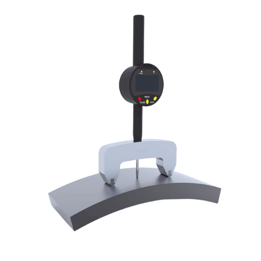
In measuring and verifying bend radii, specialized tools such as radius gauges, a digital protractor, and a CMM machine are integrated for proper and accurate measurements. Digital protractors can measure angles with precision, radius gauges compare the set radius bends to template bends, while CMMs allow for detailed four-dimensional verification of the bend dimensions. Each tool is selected according to the accuracy needs and practices of the design given.
In order to achieve consistent and precise bend radii, fabricators need to follow the basic practices dictated in the list below.
These steps, observed carefully, will help fabricators achieve better accuracy and dependability while further diminishing the chance of errors.
Using these strategies, manufacturing firms can enhance the ability to produce parts with consistent bend radii, thereby ensuring all parts conform to design and quality standards.
Bend radius accuracy requires sophisticated technologies to simultaneously monitor quality at high levels. In the list below, some of the systems that do this with high accuracy are shown is presented.
3D Laser Scanning
3D laser scanning devices enable non-contact measurement of features such as bend profiles. Modern systems can obtain geometric data with an accuracy of as good as ±0.02 mm. This method permits parts to be analyzed as they are produced, ensuring that they meet the design requirements. It is useful for complex or tight-tolerance applications.
Coordinate Measuring Machines (CMMs)
CMMs are capable of measuring the radius of a bend with a high level of accuracy. Many systems can achieve accuracy levels within microns. This ensures that the bend radius will be offset as little as possible. CMMs also have the capability of storing measurement data which is important in capturing the information for traceability, which is important in the aerospace and automotive sectors.
Digital Profiling Tools
Advanced integrated systems for digital profiling use laser or vision sensors to measure the bend radius along a part in a few seconds. These tools, which accelerate the integration phase, are often connected to CAD systems, and they permit direct comparison between the measured and theoretical values. Such integrations help in streamlining the approval process.
Force-Torque Sensing During Production
Inaccuracies occurring during the bending process can be assessed in real-time by inserting force-torque sensors into the bending equipment. Changes in the applied force may relate to problems with the bend radius and therefore, appropriate steps can be taken before a part moves to the next stage of production.
Statistical Process Control (SPC)
With SPC, bend radii over time are one of the many data points that can be captured and analyzed to help determine if any action needs to be taken to maintain identified trends. Control charts allow manufacturers to capture and mitigate process variations that may lead to defects, thus reducing waste and ensuring processes are reliable.
Comparative Analysis with Reference Samples
Manufacturers can easily check compliance of production parts with the simplistic reference samples by use of portable gauge systems set to measure the detection of the variance from the sample bend radius provided.
The accuracy of measuring the bend radius may be undermined when standard methods are used, but these state-of-the-art methods and devices work together to not only ensure quality but also enhance efficiency while reducing cost impact due to rework and material wastage.
Springback occurs when a material resumes its original form after bending, which causes discrepancies in the desired bend radius. Mechanical properties such as yield strength and modulus of elasticity deeply influence this effect. For example, high-strength alloys such as stainless steel or titanium show greater springback compared to softer materials like aluminum.
To counteract spring back, precise over-bending is also effective where the material is allowed to settle down into the desired position with an allowance of the bend being set to a larger angle than required. Finite element analysis (FEA) tools are very useful for estimating the springback behavior of different materials and optimizing their bending parameters accordingly.
Variations in the materials such as surface layers, thickness, and chemical coatings are some of the factors, that make it more difficult to achieve the desired bend radius. These inconsistencies affect material behavior under stress and may lead to undesired results. For instance, a ±5% variation in the thickness of the material can greatly affect the accuracy to which bend is attained.
The issues are resolved using advanced manufacturing solutions employing real-time monitoring systems and adaptive control technologies which aid in determining the minimum bend radius when producing parts. Bendable parts have built-in sensors that recognize differences in material characteristics and adjust the force applied automatically. This enhances accuracy and reduces mistakes. In addition, some pre-treatment processes like annealing can make the material properties more uniform, which decreases variability and aids in better-bending results.
These approaches are supported by empirical data which confirms adaptive technologies within automated environments enhance bend repeatability by 30% in high production volume scenarios. Manufacturers make effective adjustments to predictive models that take spring back and material differences into consideration to achieve a certain level of quality while meeting the design requirements.
Bending thick materials, especially at tight radii, is challenging. These challenges include the risk of cracking the material, excessive wear on the tools, and dimensional inaccuracies. They are all a result of the concentration of stress with reduced flexibility, which is common with thick materials while bending.
To resolve these challenges, advanced bending techniques such as multi-step and rotary draw bending techniques have shown to be useful. Multi-step forming prevents cracking by maintaining the integrity of the material while distributing stress over several stages; thus, deformation is controlled by numerous actions across multiple steps. Precise control of pressure die and mandrel position in rotary draw bending reduces the chances of deformative defects that arise when attempting to form tight radii. For example, specially designed mandrels that cater to thick materials can reduce ovality by up to 40% when compared to conventional methods.
Further refinement on thick profiles is aided by advancements in material science. There has been development of high-strength alloys and other materials that possess optimized ductility in thick materials for more challenging applications. Research suggests that imposing certain pre-treatment methods like heat treatment or grain refinement has been shown to improve ductility in thick materials by up to 25%. This enables tighter radii to be achieved without compromising structural integrity.
Incorporating simulation software in the design phase aids in forecasting the behavior of materials when forces are applied to them. It helps manufacturers determine the best bending angles and tooling designs to implement before actual production begins, thus saving valuable time and reducing expenses. Studies indicate that merging simulations with practice runs can decrease material expenditure by 15%, along with lowering the number of required modifications to production tools.
With the adoption of these advanced methods and tools, manufacturers can effectively tackle the problems of bending small radii in thick materials, guaranteeing superior results while adhering to challenging design specifications.
When looking for solutions to bend radius problems in difficult sheet metal parts, a manufacturer might face several challenges such as cracking, springback, thinning of the material, and wearing out of the tools. Effective mitigation and troubleshooting methods have to be put in place to protect the integrity and functionality of the end product.
1. Cracking During Bending
Cracking occurs whenever the bend radius is too small, going beyond the material’s ductility limits. Research has shown that increasing the bend radius to a width of 1.5 times the material thickness minimizes the chances of cracking. Moreover, employing heat treatments to enhance ductility or choosing quality alloys with higher percentages of elongation can significantly reduce this challenge.
2. Managing Springback
Springback can be defined as the recovery of the material’s elastic properties after being subjected to bending, which negatively influences the accuracy of the final shape. High-strength steels as materials tend to be more susceptible to springback because of their higher yield strength. As a solution, manufacturers can integrate overbending techniques or incorporate CNC press brake systems that automatically adjust for springback in real time. Data shows that advanced press brake systems with precise controls have the ability to reduce springback deviation by up to 20%. This makes it possible to standardize the minimum radius for all bends instead of just predicting the average value.
3. Deformation and Thinning of Materials Beyond Limits
For parts with low elongation capabilities, over-thinning can be particularly problematic because it may lead to a lack of part integrity. Within simulation software, FEA tools evaluate the potentially problematic areas of thinning with precision. For both bending and thinning operations, a proper ratio of die opening to sheet thickness is 6 times to 10 times the material thickness. This ratio improves the distribution of stress on the material during the bending process.
4. Compatibility and Wear of Tools
Inconsistency in tooling leads to defective or inconsistent bends. Advanced high-strength steels notably and significantly wear the tools due to their high strength and thickness. The tool’s life can be increased by as much as 30% by using wear-resistant material such as carbide-coated tools. In addition, consistent bending is achieved through the precise alignment of tooling that is checked regularly with precise measuring tools.
Emerging Trends in Troubleshooting
Manufacturers are switching to digital-based solutions like real-time data collection and adaptive control to make troubleshooting more efficient. For example, bending equipment and machines can be fitted with IoT-enabled sensors that monitor strain and deformation during production. A reduction in defects by 25% within the first production runs can be achieved by analyzing produced data to make adjustments with the help of the sensors.
Recognizing and addressing these challenges with the proposed solutions will allow manufacturers to achieve the best results even at the most sophisticated designs. Sophisticated tooling methods, advanced procedures of materials handling, and modern technologies all greatly contribute towards increasing productivity and decreasing the costs associated with low-bend radii on sheet metal components.
A: Bend radius is the radius of the bend’s arc. In the domain of precision sheet metalwork, it is always critical, as it affects the structural integrity, aesthetics, and functionality of the final product. The radius of a bend determines the minimum flange length, affects bend deduction, and also controls the strength of the area that has been bent. Knowing the radius of a bend is essential to accurately and appropriately design sheet metal parts without risking materials failure.
A: For most cases, the minimum bend radius has to be a certain number of times the sheet’s thickness. For most materials, the minimum inside bend radius is typically 1 to 3 times the material’s thickness. It all depends on the specific material properties, for example, ductility and tensile strength. Material guidelines must be referred to or experiments have to be done to find the correct minimum bend radius for a specific workpiece.
A: There are many considerations important in selecting one value of bend radius over another: 1. Material thickness and type 2. The angle of bend 3. Material characteristics: ductility and tensile strength. 4. Availability of tooling 5. Aesthetic considerations 6. Functional considerations 7. Length of flange 8. Tolerance 9. Direction of bend 10. Capabilities of the shop
A: Bend orientation is important to the area of minimum bend radius for the bend. Bending sheet metal in the direction of the grain (or roll direction) usually requires a greater bend radius than bending across the grain. This is because the material, as a rule, is not so ductile in the grain direction. Always bear in mind the bend orientation when designing the parts to be made from sheet metal so that the chosen radius will work well for the material and direction of the bend.
A: A smaller than normal inside radius can cause some problems: 1. Cracking or breaking of materials 2. Greater Springbank 3. Additional thinning of the material at the bend 4. Trouble consistently making bends 5. The short fatigue life of part 6. Increased stress concentration 7. Sharp edges pose a safety hazard Offsetting these problems by overly using the minimum bend radius specification for the material helps, but is in fact, not recommended.
A: In sheet metal work, the thickness of the material determines the selection of the bend radius. In most instances, thicker materials are more likely to fail if the bend radius is smaller than the required. The minimum bend radius is normally given in terms of the material thickness, such as 2T or 3T where T is the thickness. Moreover, the thickness determines the position of the neutral axis in bending which affects the bend deduction and the accuracy of the part in the bendable state.
A: Every radius in the bending of a sheet of metal has to be measured for accuracy in all cases. Common tools and techniques include: 1. Radius gauges or fillet gauges 2. Coordinate Measuring Machines (CMMs) 3. Optical comparators 4. 3D scanners 5. Profile projectors 6. Digital calipers with radius tips 7. Radius templates 8. Vision systems with edge detection software The use of these tools guarantees reliable measurement of the inside bend radius to keep up with the accuracy and consistency required in modern precision sheet metal fabrication.
A: For radius R and material thickness T, the procedure to determine minimum flange length is as follows: 1. consider the bend allowance (BA) 2. Incorporate tooling limits such as die opening and punch nose radius 3. Include form gripping length 4. Add trimming allowance if necessary While engaging the tool, the length of the flange is statistically at least two times the material thickness along with the bend radius. Nonetheless, for accurate deductions, it is advisable to work with the software or refer to the bend deduction tables.
1. Impact of Punch Profile Radius and Sheet Arrangement on Springback in V-Bending of a Bi-Layer Sheet
2. Influence of Punch Radius and Sheet Thickness on Spring-back in V-dye Bending
3. Influence of Punch Profile Radius on Springback in V-Bending of Transversely Welded Tailor Welded Blanks
4. The Impact of Punch Radius and Sheet Thickness on Springback in V-Bending of High Strength Steel with FEA Simulation
5. Leading Sheet Metal Fabrication Services Provider in China

Manufacturing processes are quite complex, and the choice of a production method is directly related
Learn More →
There are two major manufacturing methods for producing plastic prototypes that most people find useful
Learn More →
As a person involved or interested in the design and production of plastic components, it
Learn More →