
Manufacturing processes are quite complex, and the choice of a production method is directly related
Learn More →
Perfecting CNC machines is a prerequisite to getting the best results in precision manufacturing. Unfortunately, even the most skilled machinists experience issues such as retract marks and poor tool paths which affect tool quality and increase production time. This article delves into the details of retract marks as well as tool optimization and offers practical solutions for improving surface quality, decreasing cycle times, and increasing machine productivity. Whether you are a professional in the field or an enthusiast looking to improve your CNC machining skills, this thorough guide aims to provide information on effective techniques that will certainly enhance the quality of your work.

Retract marks on the CNC machine arise from the tool withdrawing from the workpiece after machining is done. Such features are due to differences in tool force, shoddy feed rate, or rough workpiece surfaces that generate marks on the material. Other major factors are poor tooling path definitions, ineffective cooling or lubrication, and poor machine setup. These gaps can be improved, for example, by better toolpath definitions and improving lubrication, which leads to retraction marks reduction.
Achieving high levels of precision within machining processes heavily relies upon the incorporation of the spindle and tool. The spindle is tasked with the impartation of a rotational movement alongside control of the tool’s stability during the machining process. Furthermore, the tool is responsibly engaged in the cutting operation. To boost vibration reduction as well as cutting precision, the spindle and tool must be perfectly aligned and balanced. Other aspects that influence this interaction are spindle speed, tool material, and tool geometry. Matching the capabilities of the cutting spindle and the specifications of the cutting tool enhances performance while decreasing wear and increasing the quality of the surface finish.
While retract speed is an integral component during machining processes and determines the quality of the surface finish, it has to do with the rate at which the cutting tool withdraws from the workpiece after a machining pass is completed. An idealized retract speed guarantees material build-up is at a minimum and does not lead to burr formation on the surface while maximally retaining surface quality. On the other hand, if the retract speed is too high, the tool can disengage abruptly which leads to surface quality imperfections such as ridges and grooves.
Research suggests that smooth surfaces can be achieved through a slow and gentle retract speed which allows the tool pressure to be consistent during withdrawal. For example, in high-precision milling and turning, a retract speed value of 50 – 100 mm/min is hypothesized to improve the surface roughness parameter (Ra) by 20% when compared to increased speeds regardless of material properties. Moreover, there is a balance between retract speed and cycle times where efficiency can be maximized without compromising quality.
Today’s CNC systems tend to automate retract speed control, enabling machinists to set parameters according to their materials and operational needs. Softer materials like aluminum or plastics may allow for rapid retraction, while harder alloys like titanium require slower retraction to avoid tool wear and surface abnormalities. Calibrating and testing with feedback from surface metrology tools can offer further understanding, as these retraction speed adjustments can improve finish and productivity.
The coolant’s application is essential for controlling the heat impact and the surface of the part during the machining process. Coolants reduce thermal deformation, which occurs due to overheating at the tool-workpiece interface, usually resulting in surface deformation. Reports suggest that the use of optimized systems for coolant delivery can lower the temperatures during machining by as much as 30 %, lessening the chances of discoloration or residual marks from the tools striking the part.
In addition, the removal of chips and coolant emulsion enhances cooling by preventing the cooling fluid from re-entering the cutting region. For example, the use of emulsion-based coolants containing surface active additives specifically designed for lubrication and heat transfer enhances the surface finish of machined components by reducing tool wear and stabilizing the cutting force. Advanced cooling technologies like Minimum Quantity Lubrication (MQL) or cryogenic cooling deliver optimum value for certain materials, exhibiting a reduction in surface roughness which still meets the high industrial requirements. To tap into these paybacks, the companies must consider the chemical makeup of coolant, its delivery pressure, and the pattern of its flow as the major components in the machining approach.
The distance the tool moves vertically upwards, post-operation, is termed ‘retract height’ in CNC machining. For every machine pass, the tool needs to have vertical clearance, and setting the retract height ensures that this clearance is achieved. Setting this parameter properly is very important as tool collisions need to be avoided while machining efficiency is maximized.
A well-known method involves setting the retract height based on the geometry of the workpiece and the fixture. For example, more complex machined parts that have contours or parts that are clamped by multiple clamps require a higher retract height- usually around 0.1 to 0.25 inches (2.54 to 6.35 mm). If retract heights are set too high, the machine cycle times increase, and therefore, production rates decline. According to research, reducing unnecessary retract movements can save machining time by as much as 15% with frequent toolpath change scenarios.
Moreover, advanced CAM software capable of dynamic retract adjustments allows for the automatic variation of retraction height relative to the surrounding surface. This helps optimize cutting speed with safety and is particularly effective in high-speed machining settings. Virtual modeling provides an ideal opportunity for manufacturers to analyze toolpath simulations and adjust parameters set for collisions and clearances in order to achieve the perfect optimal solution.
To help ensure high-quality materials and protect the tools, balancing the feed rate and RPM is necessary for achieving effective machining processes. The term feed rate describes how quickly the cutting tool moves through the material, while RPM signifies how quickly the spindle or tool spins. Optimal feed rate and RPM balance contribute to the ideal chip load which in turn decreases tool wear and material damage.
An example of calculating the feed rate may start with a multiplication of the chip load per tooth by flutes (cutting edges) by the spindle speed. For instance, with a standard chip load of 0.003 inches per tooth during aluminum machining, a tri-fluted tool with a spindle speed of 15000 RPM has a calibrated feed rate of 135 inches per minute (IPM). Nevertheless, this is subject to change depending on the material, the geometry of the tool, and the coolant employed.
Modifications in automation can be realized by monitoring the tool load and adjusting feed and speed parameters in real-time. For example, adaptive control machining systems incorporate real-time optimization of cutting processes to both maximize productivity and minimize the likelihood of too much force being applied which may break the tool. Furthermore, newer toolpath strategies such as high-efficiency milling (HEM) use a combination of less radial engagement with higher feed and spindle speeds resulting in an improved material removal rate.
A preliminary step in finding the best balance between feed rate and RPM involves checking the manufacturer’s cutting data for the particular material and tooling. Other important aspects including surface finish, heat, machine stability, as well as precision, and economy should also be taken into account. The use of simulation tools or digital twins improves the ability to experiment with the machining parameters without actually applying them.
Deciding on the toolpath strategy has to be set well in advance to get an optimal setup for the CNC machine. Reamed holes, for example, are features that need to be put into consideration when deciding part geometry, material type, and machining objectives. One of the newly developed strategies is called adaptive clearing, and it’s focused on removing as much material as possible while keeping the tool engaged with the workpiece for the longest amount of time and minimizing cutter overload. In comparison to traditional machining methods, adaptive clearing has been suggested to reduce machining times by 40%.
Finishing operations with toolpaths used in contour and parallel roughing have, as far as is known, been used to refine complex geometry surface contours and get good surface quality. The introduction of high-speed machining (HSM) techniques has also improved the accuracy and efficiency of these strategies. There is recent evidence that HSM decreases the machining error with a concurrent increase in the surface finish rate of about 30%.
Further, certain strategies of tool access and retraction effectively shorten tool life while increasing the total machining time. To reduce the impact loads and thus the wear rate of the tool, helical and ramped entries are often used. When used with verification software, these methods can produce reliable results with no errors or collisions during execution while preventing collision or errors from occurring.
Using state-of-the-art CAD applications and simulation resources like Autodesk, manufacturers can refine toolpath strategies, enhancing productivity and guaranteeing exceptional results for sophisticated machining processes.

Three basic components are vital in lowering tool marks through precision CNC milling techniques: the appropriate tool must be chosen, the feed rate must be optimized, and the finishing passes must be effective. There is a lessened chance for surface flaws with the use of high-quality tools with the appropriate coatings due to less friction and wear. Marked ideal feed rates guarantee that optimal material is removed with no rapid changes that can leave marks. A fine finishing pass will be applied at the end of the last machining process to aid in surface refinement and enhancement. These measures with combine to elevate the quality of a machined component.
The effectiveness and precision of machining manufacturers are greatly enhanced through the use of CNC machining simulation tools. Operators are able to see and practice the steps of machining in a simulated environment before commencing actual work. The simulations save materials and machinery from damage by identifying potential problems like tool collisions and faulty toolpaths in advance. Additionally, these simulations make it possible to fine-tune machining parameters which guarantees accuracy in every operation. In the end, simulation tools increase productivity and minimize costs which makes these tools fundamental in contemporary manufacturing.
Advanced coolant systems are definitely at the forefront of modern-day machining as they enhance tool life, part quality, and operational efficiency. Coolant’s primary responsibility is to absorb the heat produced during machining operations, lower friction, and remove chips from the cutting zone. Breakthroughs in coolant application methods, including high-pressure coolant delivery systems and minimum quantity lubrication (MQL) enhance the performance of the machining process.
As an example, high-pressure coolant systems operate at pressures ranging from 70 to 1,000 bar, having a superior cooling effect and better chip evacuation in deep hole drilling or other heavy-duty operations. Recent studies indicate that such systems can improve surface finish and extend tool life by as much as 300% in some cases.
While MQL, on the other hand, directly applies a fine mist of lubricating oil onto the tool and workpiece, significantly reducing coolant consumption. This technique not only helps in reducing operational costs associated with coolant purchase, use, and disposal but also helps in protecting the environment. Studies show that using MQL can cut down on lubricant usage by as much as 90%.
In addition, the implementation of sophisticated sensors and monitoring systems on coolant delivery systems makes it possible to measure and control flow and pressure in real time. This guarantees maximum effectiveness with regard to machining conditions while also protecting the system from overheating and tool failure.
Equally as important is the choice of coolant type, which can range from water-soluble coolants, synthetic coolants, or semi-synthetic oils depending on the material and parameters of machining. Each of these options provides distinct benefits from better lubrication to better cooling, proving the need for bespoke solutions depending on varying manufacturing requirements.
With careful system design and routine maintenance, manufacturers can achieve the desired operational performance while minimizing waste, energy use, and costs related to machining processes by amalgamating these innovative practices.

The use of CNC software in our machining processes aids in automating operations and optimizing tool paths. This automation improves the accuracy of work, reduces time spent on cycle processes, and minimizes manual input errors. Plus, predictive maintenance and real-time monitoring offered by more advanced software increase machine use and reduce downtime. When combined, these capabilities enormously enhance overall productivity in a systematic and regulated manner.
Automation within manufacturing technologies has transformed the industry in terms of productivity, accuracy, and growth potential. More and more modern machining manufacturers seem to be employing automation through the use of robotics, artificial intelligence (AI), or even IoT (Internet of Things) systems. Recent studies show that the incorporation of automation within the manufacturing processes can enhance the production output by 30% and decrease operational costs by 20%.
An example of this is robotic systems that can precisely and quickly conduct repetitive tasks. This results in less human error as well as waste in production. AI tools provide valuable data insights through predictive analytics for equipment maintenance ensuring a smooth flow of production. Furthermore, process control is enhanced by IoT connectivity. Equipment and production lines are monitored and controlled in real time resulting in faster response to problems that need immediate attention.
Moreover, automation leads to less dependence on manual labor in performing hazardous jobs which contributes to a safer work environment. Automated systems are capable of functioning around the clock which allows manufacturers to satisfy the growing needs of consumers with no impact on quality and consistency. These developments have made automation vital in gaining an edge against competition in the highly volatile world of manufacturing.

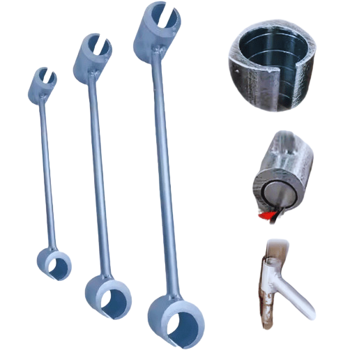
Effective identification of tool wear on CNC machines is necessary for maintaining accuracy, productivity, and cost-effectiveness. Both reamers and end mills undergo wear due to high-speed machining and interaction with materials over time. This wear can occur in many different ways such as abrasive wear, chipping, and edge formation.
Types of Wear and Indicators
Flank Wear:
Crater Wear:
Chipping or Fracture:
Built-Up Edge (BUE) Formation:
Visual Inspection:
Tool Condition Sensors:
Surface Quality Assessment:
Working Dataset Practical Insights
Recognizing these trends and adopting preemptive actions like predictive maintenance and setting proper machining conditions effectively lessen the amount of idle time while increasing tool effectiveness.
To assess the working conditions for the tool life, consider these three factors:
Observing these primary parameters and checking tool wear systematically will enhance operational productivity and efficiency as well as improve the tool’s life.
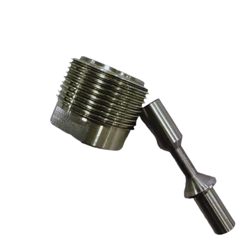
The following elements are crucial in ensuring that the tool and workpiece material are compatible:
Matching tooling parameters with the properties of the materials helps achieve optimal machining efficiency as well as precision.
A: Retract marks are marks that occur as a result of a tool being retracted from a surface during the machining process. To minimize these marks, optimize your retract rate, feed, Z-axis retraction movement, and tool strength. Sometimes using G85 (a boring cycle) instead of G81 (a drilling cycle) helps minimize retraction markings.
A: When selecting tools, take into consideration the material type, estimated quality of surface finish, surface processing, and other machining relevant processes. Ensure that tool diameters, flute numbers, and coating types are appropriate for the desired machining process. Apply and take advantage of CAM software solutions to empirically test and optimize toolpath design to shorten cycle times and increase the efficiency of machining operations.
A: With a Haas machine, here is how to best approach reaming: Use the correct reamer for the hole you wish to create, which is usually 0.01 – 0.02 mm smaller than the targeted diameter. Ensure the proper use of fed rates and spindle speeds (approximately 1000 RPM). Check the alignment and cutting fluid used so that the surface finish is better. For more refined results, consider the use of carbide reamers to increase tool longevity.
A: To perform high-precision machining you need to focus on: The use of high-grade cutting tools and rigid tool holders. Correct workpiece fixturing to decrease vibration. The use of advanced feed rates, including retracting feed, along with optimum spindle speeds. Advanced CAD-CAM software for better accuracy in toolpath generation. The application of thermal compensation and more frequent machine calibration. Try finishing processes like honing or lapping if you need ultra-tight tolerances.
A: The most important aspects one should focus on are the reduction of quick movements and improving cutting methods, as well as a selection of proper step-over and step-down ratios. Adopting trochoidal milling techniques for effective material removal. Reducing tool erosion by optimizing entry and exit tool motion. Advanced strategies of CAM like adaptive clearing and rest machining also increase precision. Remember to always focus on what is fundamentally important for the machining operation and the material first to achieve a proper balance between efficiency and surface quality.
A: Surface finish on chamfers can be worked on by following these suggestions: Employ a chamfer tool or an end mill designed specifically for chamfer machining. Pay attention to the cutting speeds and feed-per-tooth rates for the material you are working with. Minimize the tool holder runout and maximize the rigidity. Climb milling should be used to improve surface finish where possible. Use micro-shift cutting techniques, also known as finishing passes. For rough parts, programs with advanced CAM systems are helpful. They will optimize the tool motion paths so that roughing and finishing passes maintain steady axial chip thickness efficiently.
A: Decrease the chances of tool breakage by adopting the methods outlined below: For each material and type of work, choose the correct tool to ensure efficient performance. Make use of feed per minute and rotational speeds, while taking into account the retract feed performance. Employ an effective coolant strategy. Ensure that the optimized tool path is followed for precise chip thickness. Make prompt changes with worn tools and carry out visual inspections frequently. Cycle activity sets that create a load that is too high should be supplemented with tool control. Workpieces that vibrate should be properly fixed with frames. Like this, the vibration is significantly reduced.
1. Title: A Study on the Errors That Cause Irregular Tool Mark Patterns on a Twisted Ruled Surface in Flank Milling of a Five-Axis CNC Machining Center
2. Title: A G3 Continuous Tool Path Correction and Smoothing Method for CNC Machining.
3. Title: Accounting for Errors of CNC Machines and Tools in Tool Marks Calculations
Manufacturing processes are quite complex, and the choice of a production method is directly related
Learn More →
There are two major manufacturing methods for producing plastic prototypes that most people find useful
Learn More →
As a person involved or interested in the design and production of plastic components, it
Learn More →