

Manufacturing processes are quite complex, and the choice of a production method is directly related
Learn More →
Gears drive the motion and precision of countless industrial and household machines, making them some of the most unrecognized elements within many mechanical frameworks. The correlation between the movements of gears is termed gearing, which comprehensively elucidates the workings of gears and is crucial for devising proficient and accurate mechanical systems. This guide aims to solve the intricacies of gears and gearing by studying their principle, form, and function. Be it an engineer, a hobbyist, or just a curious person who wishes to learn about the inner workings of mechanical systems, this article will help widen your scope on the functionality of gears and provide deeper insights into their importance in the modern world. Join us as we discuss how these functional parts convert rotary motion into a helpful movement.
A gear is a rotating part of a machine with teeth or cogs designed to mesh with another component to convey motion and torque. Gears shift rotary power from one shaft to another, frequently changing speed, direction, or force. This is done by the accurate interaction of their teeth, guaranteeing uniform and coherent motion. Gears play a vital role in the functioning of machines; they are implemented in almost all purpose-built devices, such as cars, industrial machines, and timepieces, to increase their functionality and effectiveness.
Tools transmit force via the teeth meshing, enabling the transfer of rotational force to rotate an object. One gear rotates and applies force to the connected gear, which causes it to rotate. By changing the size of the teeth and the number of teeth on each gear, the torque and the rotation speed are adjusted. For instance, when a more significant gear transfers force to a smaller gear, the speed increases while decreasing the torque. The opposite will result in increasing the torque while reducing the speed. Principles like these make gears efficient in the mechanical system to perform specific tasks.
There are various sorts of gear profiles, each one being suitable for specific applications, such as:
Every type of gear is designed differently, depending on outdated features such as speed, torque, and directional movement.
Machines’ movement and load power are transferred between their parts through motion systems to achieve proper power, speed, and rotation direction. Motion transfers from one gear to another as each gear’s teeth fit into each other. The interplay of the gears determines the speed and force that can be achieved based on their arrangement of teeth, which is referred to as gear ratio. Misalignment and lack of lubrication may increase the chance of damage, so preventive maintenance is required for proper functioning. Numerous technology barkers, such as automotive systems, industrial equipment, and machinery, utilize industrial, mechanical, and specialized gears as their components.

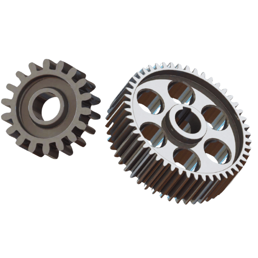
The most prevalent category of gears, spur gears, feature straight teeth that are parallel to the axis of the gear and are typically used for the transmission of motion and power between parallel shafts. Spur gears have a relatively high-efficiency rate, are easy to fabricate, and generate a small amount of axial thrust while functioning. On the other hand, their performance at high speeds causes teeth to come in contact with one another, suddenly resulting in high noise levels. These gears are generally employed in fields that require high accuracy, such as mechanical drives, conveyors, and clocks.
Helical gears are highly preferable for situations where noise-free and seamless operation is imperative. Their teeth are positioned at an angle and enable gradual engagement, which helps reduce vibration and noise. Therefore, they operate smoothly, even at heightened rotational speeds or under high loads. They are often employed in the automotive industry’s transmissions, conveyor systems, and industrial machines that require a lot of power and are durable.
Worm gears are employed in scenarios that need high torque and slow output. Their peculiar design, consisting of a worm (screw-like gear) working interdependently with a worm wheel, makes possible great speed reductions alongside the achievement of load-holding capability without brakes. Elevators, conveyors, and hoists are examples of equipment that benefit from their use, as these devices need self-locking movement control and precise motion control capability. Additionally, worm gears are appreciated and used due to their reliability, efficiency, and compactness in power transmission.
To find the gear ratio of a gear train, divide the number of teeth in the driven gear by the number of teeth in the driving gear, mathematically expressed as:
Gear Ratio = Teeth on Driven Gear / Teeth on Driving Gear
This ratio indicates the distribution of speed and torque within the system. The higher the gear ratio, the lower the speed and the higher the torque. The smaller the gear ratio, the higher the speed and the lower the torque. So, always measure the number of teeth accurately to get accurate results.
The gear ratio profoundly impacts the mechanical performance of any system in terms of torque and rotational velocity. For example, a higher ratio of 4:1 indicates greater torque and lower rotational speed. This is useful in automotive scenarios that require heavy load movement, like ascending hills. The high torque allows vehicles to overcome resistance more, which helps them during such movements. In contrast, lower ratios like 1:1 or 2:1 enable speed rather than torque and suit high-speed driving conditions on a highway.
A bicycle’s gear ratio is a powerful example. Micrometric power output may make pedaling harder for a steep climb, but the output increases at some pedal rotation. Conversely, a more effortless and quicker pedal causes output reduction. Likewise, in industrial gear trains, a higher tooth count relative to the driven gear reduces torque at the driven shaft while significantly increasing the rotational speed.
Modern analyses in automotive engineering suggest that for each step increase in gear ratio, torque amplification rises at an approximate rate of twenty percent, while speed output rotates. These adjustments enable special applications like machines and vehicles to be used optimally by tailoring the system according to performance requirements.
References to mechanisms of reduction can be found in many everyday appliances. Some examples include:
These appliances serve as instances of enhancement offered by reduction mechanisms and are almost universally used.

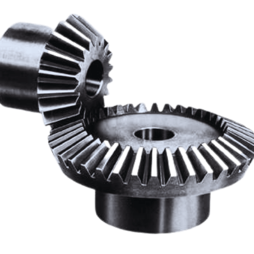
Bevel gears efficiently transmit power between two shafts at an angle to each other, usually 90 degrees. They use conical-shaped teeth that are cut to mesh perfectly when placed on two intersecting shafts. This modification enables them to shift the direction of rotational power promptly.
Bevel gears are used in automotive differentials to redirect torque from the driveshaft toward the axles, which, in most cases, requires a considerable gear reduction. By effectively distributing torque between the wheels, the gear above allows vehicles to make smooth, controlled turns. Such gears are also employed in the industrial sector in machinery like conveyors or packaging tools that require precise power delivery at set angles.
Engineers have optimized the design of bevel gears by using heat-treated steel and advanced manufacturing technologies, which guarantee high durability and load capacity. The performance of these designs can reach a 97% efficiency ratio relative to the application. Moreover, a variation of these gears, the hypoid bevel gears, enable better torque delivery with lower operational noise, making these ideal for heavy-duty or performance-sensitive systems.
Bevel gears still serve a key function in modern engineering mechanisms because they enable the meticulous redirection of angular power.
Because of their capacity to efficiently transfer power, particularly at a high torque level, and their smooth and quiet operation, hypoid gears are often used in the automotive industry. They are used specifically in the design of rear axle differentials, which allow for an angular offset between the input and output shafts. This offset feature lowers the driveshaft, decreasing the vehicle’s center of gravity and thus improving its stability and handling.
For SUV and truck automotive applications where durable hypoid gears are needed, the capacity to handle high torque loads is unmatched in standard vehicles. Modern hypoid gear systems can achieve up to 40% torque density compared to traditional bevel gears. The hypoid gears also have a better-curved tooth geometry, which provides lower engagement, lower wear, and increased durability, which helps maintain the components of a vehicle that are continuously used.
Today’s automotive industry values fuel economy, and low-viscosity synthetic lubricants used with hypoid gears help reduce friction and heat generation, increasing fuel economy efficiency. This is especially important when using ring gears. These characteristics make hypoid gears one of the most essential parts of modern automotive engineering, balancing performance, efficiency, and durability.
The primary difference between standard bevel gears and their counterparts, spiral bevel gears, lies in the design and performance of their teeth. Unlike standard bevel gears, whose teeth are straight, spiral bevel gears have curved angled teeth, which provide smoother operation and quieter noise. Because of this, spiral bevel gears experience lower vibration and higher efficiency. Therefore, they are perfect for tasks that are precision and durability-centered.
Unfortunately, standard bevel gears experience a setback in construction complexity and ease of machining, resulting in lower production costs. This manufacturing inefficiency dominates domains where noise control and performance demand are less stringent. These standard gears, with the hand of time, suffer increased wear and tear and noise due to the straight teeth’s sudden engagement.
In short, spiral bevel gears win the trophy for torque and performance in precision applications. Standard gears, which keep their name simpler but are cheaper, are bound to moderate performance.

A rack and pinion gear system can also be described as the conversion of rotational movement into straight-line movement using two components: a rack, which is a flat strip with teeth, and a pinion, which is circular and toothed. When the pinion turns, its teeth interact with the rack’s teeth, resulting in the rack moving linearly. This movement is very useful in steering systems, machining tools, and automated systems. The setup of this system is uncomplicated and effective and is, therefore, easy to depend on when trying to convert rotational movement to directional movement.
Rack-and-pinion systems are preferred in steering mechanisms as a single-gear configuration due to their simplicity, precision, and reliability. These systems permit effortless and accurate control because the steering wheel’s rotation is directly related to the linear motion needed to turn the wheels. This improves handling accuracy and minimizes the force required to steer. Such systems are often employed in passenger vehicles, where compact and effective systems are required.
When looking at alternative gear mechanisms, we notice that the rack and pinion systems have a great number of benefits. To begin with, their design contains very little motion loss. That is very efficient for applications requiring high speed and responsiveness, like steering systems. Secondly, rack and pinion systems are more compact and lighter than other more complex gear systems, which is crucial for systems with limited space. Moreover, they provide smoother and more exact linear movements to guarantee accurate operations for vehicles and industrial machines. These features demonstrate how practical and flexible the different types of gears that make rack and pinion systems are and how we may utilize them in modern engineering.
A: An involute gear is one of the most common gear profiles in gear design because it provides smooth and consistent power transmission. The involute gear’s importance is that the center of each gear within the set remains constant during meshing, making it a simpler and more efficient operating system to manufacture.
A: A herringbone gear has V-shaped teeth that make it easier to counteract the axial thrust experienced in helical gears, making it more stable and smoother. Unlike standard gears, herringbone gears are employed in much noisier and heavily loaded types of machinery.
A: A gear cannot turn the worm because of excessive friction and obstruction of some parts of the teeth of the worm wheel, making the reverse motion very difficult. This makes the work prismatic and suitable for all applications where accuracy and prevention of reverse movements are considered essential.
A: The number of teeth on the gear determines its speed ratio and torque output. An increase in the number of teeth on the driven gear compared to the driver gear leads to increased gear reduction, which lowers the speed of the driven gear while increasing torque.
A: Gears are fundamental to a vehicle’s performance. Lower gears, such as the first gear, provide maximum torque and acceleration at slow speeds, while higher gears, like the top gear used during cruising, are more efficient and place less load on the engine at high speeds.
A: The contact point in gear meshing is most important because it governs the load distribution and smoothness of the transmission. If the contact point is aligned correctly, wear, and noise will be reduced, extending the lifetime and efficiency of the gear set.
A: Helical gears are used in transmissions because their arrow-shaped teeth provide smoother and quieter operation than straight-cut gears. The engagement process of teeth on helical gears is gradual, significantly reducing shock loads and making them highly durable for high-speed applications, which is required for large gear reduction systems.
A: The traditional forms of gears like spur and bevel introduced essential concepts of torque transfer and speed ratio; this seabed was the basis for modern gear design. These important functions are built upon by more complex advanced gears like helical, herringbone, and involute, which deliver more efficient solutions.
A: Two gears engage with one another through the alignment of teeth, transferring motion and force. When proper meshing occurs, the teeth of the individual gears slide into each other, enabling the transfer of power without slippage. This means the system can achieve the desired speed and torque output.
1. Nonlinear Torsional Dynamics Of Star Gearing Transmission System Of GTF Gearbox (Wang &Zhu, 2020)
2. Gear Geometry and Applied Theory: Gear Geometry and Applied Theory (Litvin & Fuentes, 2004)
3. Gear
4. Gear train

Manufacturing processes are quite complex, and the choice of a production method is directly related
Learn More →
There are two major manufacturing methods for producing plastic prototypes that most people find useful
Learn More →
As a person involved or interested in the design and production of plastic components, it
Learn More →