

Manufacturing processes are quite complex, and the choice of a production method is directly related
Learn More →
As an engineer, you should understand that drilling and machining are both primary and essential processes in the manufacturing sector. They are the backbone of prodding, modifying, and fabricating systems that need materials to be remodeled using precision tools and equipment. In this blog, I provide a general explanation of the processes and techniques involved in these operations, Vol. 1 guides readers in learning the basics of boring; an advanced form of machining which enlarges, refines, and achieves precise tolerances to already existing holes. Professionals, students, or anyone who takes a general interest in engineering will learn in this post the fundamentals of the term CNC in modern industry.
Both drilling and boring are procedures done in machining, but neither serves the same use or function. In drilling, a new cylindrical hole in a material is created using a rotating cutting tool, which is typically a drill bit. It is meant for initial roughing of a new hole. Boring, however, is done to increase the size of refined holes, making them more accurate in terms of diameter and surface finish. While boring is most often the secondary operation, there are cases when it is the primary operation, and the hole to be drilled is more precise and has better dimensional accuracy and tolerances.
To define the difference between drilling and boring, certain feceonic values can be compared. Boring does not require high RPMs, the usual range of the drill bits is between 500-3000 RPMs depending on the material being worked on. Also, drill bits have an extremely wide range of diameters from 0.5mm to over a hundred mm. These bits are useful on multiple sectors spanning manufacturing, construction, electronics, and even on the assembly of devices.
Unlike other operations, boring is more precise and much slower, averaging between 300 and 1000 RPM. Depending on the finishing, tools are capable of achieving surface roughness values up to Ra 1.6 µm. Moreover, many boring operations accomplish tolerances of ±0.01 mm, which is vital for aerospace and automotive engineering.
These distinctions elucidate the notions of drilling and boring in conjunction to the structural integrity and dimensional accuracy of the fabrication processes.
The boring machining process contains precision parameters and other considerations that can easily affect efficiency and accuracy. Below are some of the critical factors and their respective typical values.
Typical Range: ±0.01 mm to ±0.05 mm (based on varying application needs)
Importance: Guarantees compliance with stringent dimensional tolerances reasonable in some industries.
Measured as Roughness Average (Ra): Typically Ra 1.6 µm or lower
Application: A smooth surface is imperative to minimize friction and wearing down of parts that are already assembled.
Speed Range: 60 to 300 m/min (depends on material)
Feed Range: 0.05 to 0.5 mm/rev (depends on the application)
Common Choices: HSS, Carbide, PCD
Selection Criteria: Based on the material of the workpiece and the finish required.
Commonly Used Materials: Steel, Aluminum, Cast Iron, Titanium.
Difficulties: Each material may need its own unique tool and its own unique method of cutting.
Rough Boring: Takes out big chunks of material at a greater feed rate.
Finish Boring: Concentrates on high accuracy with great surface finish.
Manufacturers can optimize these factors to improve repeatability, reduce cost, and maintain the quality of the parts being machined.
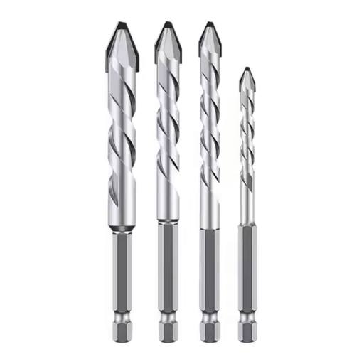
Drilling is defined as the production of a hole through solid material by means of a rotating cutting tool called a bit, typically used at the start of machining. It removes a specific amount of material to form a cylindrical cavity without much attention being paid to its depth, diameter, and smoothness. Boring is the additional machining process of enlarging, refining, and finishing of holes to very close tolerances. It brings the best accuracy, least tolerance, and maximum surface increases. Drilling is known for its faster removal of material with the first few cuts; however, boring determines the final details in all works needing accuracy such as in automotive or aerospace engineering.
While choosing a boring tool, important considerations such as the material and the tolerances needed along with the diameter of the hole are necessary. Boring bars are particularly made of tough materials like carbide and high-speed steel because they are accurate and strong. For instance, harder materials or higher speed operations tend to use carbide tools because they are durable and maintain their cutting ability over time.
The dimensions of the tool also greatly matter. A rough rule of thumb is the boring bar diameter must be at least 10 percent smaller than the hole diameter in order to minimize vibration. For example, the ideal boring bar diameter is 18 mm or less when the hole diameter is 20 mm. Moreover, in operations with tighter tolerances, higher precision can be obtained with vibration dampening mechanisms like specialized coatings and dampers.
Another of these characterizing features is the spindle rotation speed together with the feed rate, since they affect surface finish and material removal. As an example, soft parts like aluminum could utilize a spindle speed of 300 revolutions per minute with a feed rate of 0.1 millimeters per revolution. On the contrary, harder materials like steel necessitate modifications, which frequently means reducing speed and feed to preserve tool life and secure an adequate finish. Proper application of coolant also reduces heat produced while extending the life of the tool during complicated boring processes.
In order to obtain the most exact diameter possible during boring operations, certain parameters must be kept in mind. The information provided below should help guide the process:
Soft Materials (Aluminum for example):
Spindle Speed: ~300 RPM
Feed Rate: 0.1 mm/revolution
Usage of coolant: Use sparingly
Hard Materials (Steel for example):
Spindle Speed: ~150-200 RPM
Feed Rate: 0.05-0.08 mm/revolution
Usage of coolant: Applied constantly to reduce heat buildup
Tools for selected materials:
High-speed steel (HSS) tools: For softer materials, yes
Carbide-tipped tools: For harder materials, yes
Geometry of the tool:
Positive rake angle for reduced cutting forces needed
Proper tip radius for surface finish requirements
Coolants:
Water soluble coolants for most general purposes
Oil based coolants for heavy duty cutting purposes
Application method:
Flood cooling for use in non-stop operations
Mist cooling for use during interruptive cutting operations
Precision of bore diameter
Pre-bore preparatory work:
First bore diameter needs to be measured as accurately as possible
Piece must be correctly located in relation to machine spindle
Final bore tolerances:
±0.01 mm for most exacting work
±0.05 mm for general work
With these factors taken into consideration and adjusted to fit both the specific material and operation, machinists are able to maintain tool life, achieve better finishes, and fulfill tighter tolerance needs successfully.
Achieving the desired qualitative outcome of surface finish in a boring operation is mostly dependent on cutting speed, feed rate, tool shape, and composition of the workpiece. It is crucial to control the cutting speed so that excessive heat is not produced, which can be detrimental to the finish. Generally, lower values of feed rate produce smoother finish values since these reduce the irregularities of material removal. Nose radius and rake angles of the tool are also extremely important for the magnitude of roughness that will be produced on the surface. Additionally, coolant or lubricant can also be introduced as it can aid in dissipating heat as well as chips, thus improving the surface texture of the workpiece. With the appropriate setting of parameters from these values, machinists are more likely to achieve quality surface finish values consistently during boring operations.
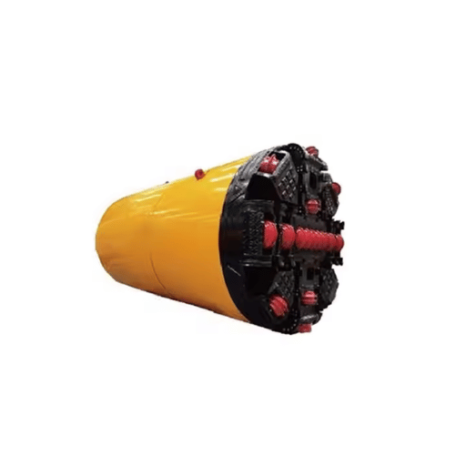
Horizontal boring machines (HBMs) are widely used in horizontal boring operations demanding accuracy and consistency. They are often incorporated into the machining of complex holes on large, heavy parts that are not conveniently portable or rotatable. With a horizontal spindle position, HBMs usually have a worktable that can support enormous workpieces. Horizontal boring machines have a number of important operating parameters, including the following: HBMs are used with large heavy workpieces that cannot be easily rotated, moved or even transported. They are also significant additions to the repertoire of horizontal boring operations.
Spindle Diameter: From 50 mm to over 250 mm, defining the diameter range of available cutting tools.
Spindle Speed: Between 10 to 4,000 RPM on horizontal boring machines is adjustable for working with various materials and different requirements for cutting.
Table Working Area: For various workpieces, it may vary from 600 mm × 800 mm to over 2,000 mm × 2,500 mm.
Travel Distances:
X-Axis (Longitudinal): Commonly ranges from 1,000 mm to 10,000 mm.
Y-Axis (Vertical): Quite frequently lies between 800 mm and 5,000 mm.
Z-Axis (Spindle Travel): Is usually from 500 mm to 2,000 mm.
Horizontal boring machines are used in automotive, aerospace, and heavy machinery industries. Their rigidity and precision make them ideal for producing accurate bores, milling surfaces, and threading. Modern CNC HBMs have varying capabilities, and depending on the model, they can also include automatic tool changers, digital displays, and software integration which all improve efficiency and decrease setup time.
VBM are perfect for use in precision machining of large, heavy, circular components. They are best used in machining workpieces that consist of engine blocks, turbine casings, and other large parts that cannot be easily rotated in a horizontal fashion. These machines are designed to perform vertical turning, facing, and cutting and are able to achieve tight tolerances on heavy parts. Most modern vertical boring machines are constructed with new features such as CNC controls, automated tool changes, and real-time monitoring, as these features help improve productivity and accuracy while reducing downtime. Their durable construction and material handling efficiency makes them essential in power generation, mining, and oil and gas industries.
Unmatched accuracy and uniformity in machining operations are guaranteed with CNC boring machines. These machines have precise linear guides and ball screws that claim to provide mechanical position and dimension accuracy of ±0.005 mm. The application of CNC (Computer Numerical Control) enables the mechanization of intricate and monotonous processes, which lowers the amount of human error and operational ineffectiveness.
Moreover, CNC boring machines provide multiple tool configurations, allowing users to carry out drilling, boring, and milling operations with no manual tool changing or setup required. This flexibility leads to decreased cycle times with improvements of productivity of almost 40% when compared to manual boring CNC machines.
Modern CNC Boring Machines are designed to easily accommodate a variety of materials from hardened steels, alloys, and aluminum to industrial grade composites. Because of such capability, those machines became paramount in the aerospace industry which requires large amounts of titanium as well as robust materials, and automotive industries where high productivity and precision manufacturing is needed.
Aerospace: Used for machining engine components with tolerances of ±0.01 mm.
Energy Sector: Producing large turbine housings (over 20 tons) requires precision working.
Automotive: Industry now enjoys a 30% cycle time reduction in the production of engine blocks and cylinder heads.
The necessity for specialists, higher productivity, as well as quality of goods in modern industries is constantly rising. For this reason, it becomes crucial to use CNC Boring machines in the manufacturing processes.
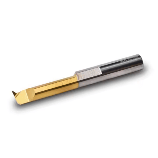
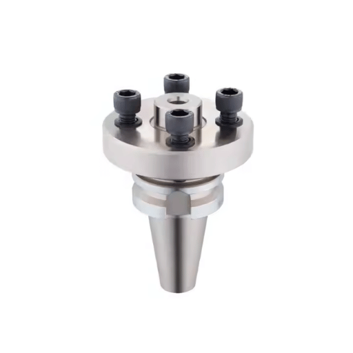
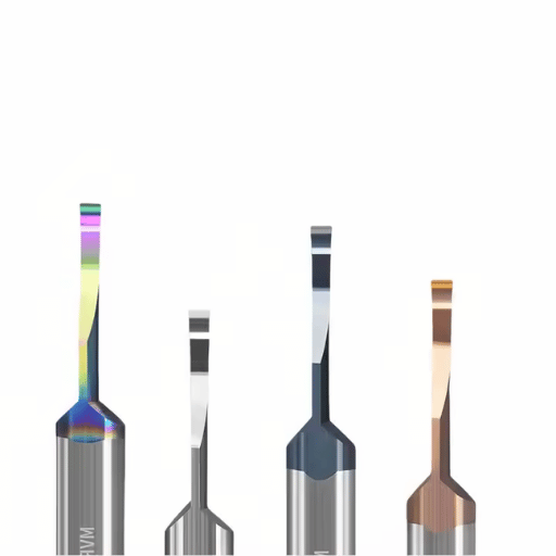
The boring operation is fundamentally dependent on a range of cutting tools that are engineered with the effectiveness and accuracy in mind. Some of the tools would include solid carbide boring bars, indexable cutting inserts, and modular boring heads. Solid carbide boring bars are known to be most effective because they are quite rigid and have good resistance to vibrations, which makes them useful in high-precision works. Indexable inserts are often made using advanced materials like tungsten carbide or cermet. The insert’s ability to be rotated and reused makes it flexible and useful for many workpiece materials like steel or aluminum. Modular boring heads are able to change the size and depth of the bore during the machining operation, which increases flexibility and decreases time spent on set-up. With the combination of these tools and modern CNC controls, consistent tolerances and surface finishes that are essential in today’s manufacturing are achievable.
Boring bars have been made to obtain a particular level of precision and performance while carrying out any metal working activities. The fundamental factors one should consider includes:?
Dimensional Characteristics: Diameter Shank Range: Mostly found in ranges from 0.25 inches (6.35 mm) to 4 inches (101.6 mm). Overhang’s Length to Diameter Ratio (L/D): It’s standard for an L/D to fall somewhere between 3:1 and 8:1, which has a reduction of rigidity along a higher risk of vibration as the ratio increases. Compatibility with Other Machines: Types of Inserts: Broad range of compatible inserts such as triangular, diamond, and round. Coating: Inserts have TiN (Titanium Nitride), and TiAlN (Titanium Aluminum Nitride) multilayer coatings the increase temperature and wear resistant. Measurement of Precision: Limits of Accuracy: Eccentricity tolerances of around ±0.0005 inches (±12.7 µm) is common for nearly all setups on the boring bar, assuming machine-tool stiffness is all sufficiently high. Surface Finishing: The high standard level of processing tends to be capable of bearing roughness of Ra 0.4 to 1.6 µm which is common in industry. Modifications for Improvement: Chip Carried Water Method: Water or other means of chip-removal processes can be delivered internally and externally to control temperature of the working tool and the machinery being worked on. Active Balancing Systems: Damps vibration, allows more stable cutting and prolongs the tool’s durability.
The choice of boring bars should match with the characteristics of the machining operations, considering factors like the material’s hardness and volume, the machining depth, tolerances, and the quantity produced. When these tools are set up correctly, they greatly enhance the productivity and quality during the execution of precision machining operations.
Reaming is the final touch of a step in a process of a precision machining that involves high level of accuracy in terms of the dimensions of holes and an improved surface. This process requires a tool called a reamer, which makes a pre-existing drilled hole larger by a small margin. Several factors determine the efficiency of reaming including tool material, geometry, and the conditions of machining.
Important Aspects and Information on Reaming Operations:
Dimensional Accuracy: Depending on the type and application of a reamer, tolerances as tight as ±0.005 mm (±0.0002 inches) can be achieved with reaming.
Surface Finish: This process also guarantees a finer and smoother finish with surface roughness values (Ra) of under 0.4 um.
Material Compatiblity:
For general use like softer materials such as plastics and aluminum, high-speed steel (HSS) reamers are acceptable and suitable.
For tougher materials like hardened steels and titanium, carbide and coated carbide reamers are dominantly the best choice due to their resistance to wear.
Speeds and Feeds:
When reaming, it is customary to operate the cutter head from 50%-60% of the drilling speed for the same material.
The feed change for reaming processes is typically between 0.03 mm/rev to 0.15 mm/rev, which affects the finish and geometric tolerance of the resulting workpiece.
Usage of Coolant:
Proper consistency of lubrication is critically important in minimizing friction and performance within high-speed applications. Temperature regulation is performed with water-based coolants.
The appropriate selection and use of the reaming tool, along with the required parameters, guarantees accuracy on the drilled hole dimensions and its quality, effectively reducing tool wear and production inefficiencies.
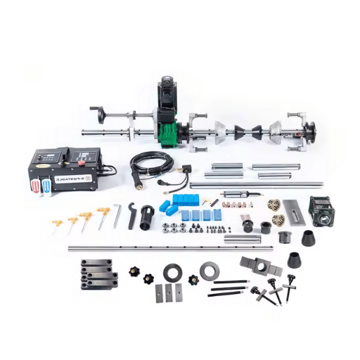
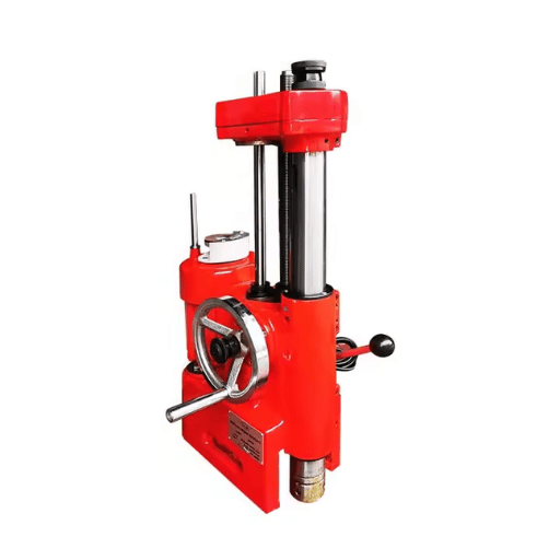
Line boring refers to the machining process of increasing the diameter, aligning, or restoring a cylindrical bore’s accuracy on heavy components of equipment, machinery, and even structures. This operation is done by moving a cutting tool mounted on a boring bar along the axis of the bore and rotating it. This is typically done on turbine casings, industrial bearings, and engine blocks.
To achieve the proper and accurate result, the workpiece and the boring bar need to be properly secured using specialized fixtures. Portable line boring devices are commonly used because of their usefulness in on-site servicing which decreases the time and effort needed when large pieces of equipment are disassembled and serviced. Some of the latest devices include automated feeds and digital distance measuring devices.
In achieving the most desired outcome, there is a need to watch parameters set for cutting speed, tool material, and feed rate while taking into account the type of material being cut. In addition, lubricating or coolant fluids are important in minimizing wear and tear, controlling the heat produced, and ensuring the correct size. If done correctly, line boring helps in extending the life of the equipment while restoring normal working conditions.
Line boring is a technique that is executed in mixed construction and related fields’ companies such as mining, marine, and energy companies where large machines and sensitive parts have high rates of wear and tear due to misalignment. Common applications include the refurbishing of excavator booms, loader arms, turbines, engines, gearboxes, and pivots on heavy equipment. Restored bores guarantee alignment of parts to be assembled and safety against mechanical failures during operation which enhances safety, reliability, effectiveness, and efficiency.
In the Order of Magnitude: Line boring machines are capable of achieving tolerances of as cool as 0.002 inches and less depending on the application and equipment used.
Machining: The cutting speed generally varies from 80 to 200 surface feet per minute depending on the type of material, as well as the tool used.
Economic: It is estimated that on location line boring will reduce the cost of overhaul that is around 50% more than off the equipment or component replacement options.
Time: Portable line boring solutions are more efficient than normal repair workflows as they tend to reduce the downtime needed by 30%-60%.
Material: Tools are normally used with carbide or HSS edged tipped cutting tools for various materials such as steel, cast iron, and bronze as they are more durable and precise.
The use of most accurate techniques and advanced equipment in line boring improve industry standards which leads to operational efficiency and cost-friendly operations.
Obstacle: Keeping Equipment Aligned
An already present discrepancy can grow worse if a machine is being worked upon and lead to further issues with both parts – the output doesn’t fit the input.
Resolution: Noticeable misalignment during and after machining operations may be corrected with the use of lasers and dial indicators for ascertaining the alignment. Further, systematic calibration of these tools also assists in reducing their margins for error.
Obstacle: Tool Wear and Material Toughness
When working with materials like iron and steel, the cutting tools become easily worn out over time, which tends to decrease precise output.
Resolution: Use of tools generated from cutting Tungsten carbide or Polycrystalline diamond (PCD) guarantees better lifetime. Furthermore, ongoing inspections and maintenance checks on tools guarantee effective use over longer timeframes.
Challenge: Limited Access in Remote or Confined Work Locations
Performing line boring in tight or remote locations involves operational and logistical challenges.
Solution: These portable line boring machines are modular, permitting their setup and use in tight spaces. Even in harsh conditions, these machines offer freedom and exceptional accuracy.
Challenge: Heat Generation During Cutting
An increase in heat retention may shorten tool life or cause dimensional distortion, both of which affect quality.
Solution: Employing suitable coolant systems and cutting fluids can aid in controlling temperature during cutting, improving working conditions while protecting the material.
For these organizations, implementing these measures will improve their line boring procedures concerning reliability, efficiency, and compliance.
Details: The use of tool steels and cast irons with higher hardness values results in higher rate of tool wear. This increases operational costs due to excessive tool wear and leads to time delays due to operational and tool changing procedures. These problems can be alleviated by choosing the appropriate tool materials, such as cobalt-tipped or coated cutting tools.
Data: Research suggests that tools cutting materials with a Rockwell Hardness (HRC) above 45 have the 20% to 30% of their life expectancy when cutting softer materials.
Details: Tight tolerances can be observed in the engine component or aerospace structures where tolerances of ±0.002 inches is common and the achievement of such tolerances is critical. Failure to meet the given tolerances can cause malfunctioning of the system or failure of the component. These issues can be solved by using modern CNC controlled bored.
Data: One survey of aerospace manufacturers noted that poor tolerance control contributed to 15% of the rework cost which emphasizes the need for precision in boring.
Summary: In boring bars, vibration and deflection are prominent problems, particularly in deep-hole boring. These phenomena contribute to the damage of surface quality and the precision of bore size. However, employing damped boring bars and fine-tuning the cutting parameters can help alleviate these impacts.
Information: Experimental data indicates that with the use of vibration-dampened boring bars, amplitude oscillations can be lessened by 50%, and surface finish Ra increases from 4.0 to 1.5 microns.
Organizations can make use of advanced tools to overcome these challenges and optimize boring processes for improved efficiency, tool life, and part quality.
Deep-hole boring is enhanced with vibration analysis which helps check and solve issues pertaining to tolerance and surface finish. In addition, excessive vibration that occurs can lead to inflicting damage to the cutting tools and alters the accuracy of the dimensions and the integrity of the surface.
Summary: The contact between the workpiece and the cutting tool brings about vibration. Working parameters such as tool overhang ratio, cutting speed, and material hardness have an impact on the vibrations. An increased deflection and chatter is caused by longer tool overhangs which makes errors likely to happen.
Studies suggest that cutting vibrations could be reduced by 40% just by decreasing the overhang ratio from 8:1 to 5:1. In addition, the application of real time vibration monitoring systems have improved part quality by over 25%, and reduced rework rates.
It is very important to select cutting parameters and tool materials as they greatly affect the heat, wear, and efficiency of the machining process.
High speed steel (HSS) and carbide are commonplace materials for boring bars, as they are able to withstand significant amounts of heat and wear. Their effectiveness is, however, heavily influenced by the cutting speed and feed rates that are adopted. Optimized feed rates yield a lower heat build up, which increases tool life and helps maintain the bore quality.
Changes of even 10% to feed rates during machining have shown to improve bore dimensional consistency by nearly 18%. Coated carbide tools are also more effective than uncoated tools when cutting metals at high speeds, especially with difficult materials such as titanium alloy, where aerospace applications make great use of.
Recent progress in boring technology has focused greatly on the incorporation of smart tooling systems and advanced coatings for precision and efficiency gains. Smart boring tools with sensor capabilities have enabled the measurement of vibration, temperature, and dimensional shift during machining processes. This innovation has improved process control, increasing accuracy by up to thirty percent. In addition, new coating materials for tools, particularly diamond-like carbon (DLC) and ceramic-based coatings, have been proven more wear-resistant and thermally stable. Evidence suggests that these coatings may enhance tool life up to forty percent when machining high-strength materials, such as nickel-based alloys. Meeting the requirements of modern machining environments where high accuracy and economical measures are essential necessitates the integration of these technologies.
A: In terms of machining, the definition of a bore is the process to increase the diameter of an already created hole by implementing a boring tool for accurate measure of the diameter of the hole.
A: Boring is a technique in machining that deals with achieving an accurate enlarged form of a hole in a given workpiece. Drilling is the action of either cutting or scooping out an initial hole with a drill bit. The bore is using a single pointed tool which cuts and it is this which gives fine accuracy and finishes.
A: Boring machining work is performed with the following main tools: lathe and milling machine. These tools are common: lathe boring, horizontal boring mills and the most common for enlarged holes, precision boring machines.
A: To put it in simpler terms for kids bare means to take something that has a smaller hole and make special tools be aimed towards making the smaller hole bigger while ensuring the right size is achieved.
A: Boring in a medical sense does not have a direct connection to machining, though if it were to be used figuratively, it refers to skillful surgical bone drilling that is performed to deepen or smoothen surgically created cavities in bones.
A: Boring is done in making the engine cylinders in order to put a very precise and smooth surface on the inner side of the cylinder. This is important for the working of engines, and the bore size of the engines greatly motivates the efficiency level of the engine.
A: from a legal perspective, boring in machining has no defined specification, but it can be found in other legal texts related to manufacturing processes or regulations which means the widening of already made holes with accurate precision,
A: The distinction between boring and reaming stems from their objective and method. Boring uses a single-point cutting tool to increase a hole to the desired dimension while reaming is used to accurately finish a hole that has already been made with a drill bit, usually after it has been bored.
A: A pilot hole is a small hole on the workpiece that guides the boring operation. Its relevance is to make sure that the final bored hole is accurate, where the aids serve as a point for enlargement and refinement of operations.
A: The maintenance of precision of a bored hole requires the use of dedicated boring instruments such as the precision boring machines, and that have control over the edge and the cavity’s tapering dimensions with a designed set of precision limits.

Manufacturing processes are quite complex, and the choice of a production method is directly related
Learn More →
There are two major manufacturing methods for producing plastic prototypes that most people find useful
Learn More →
As a person involved or interested in the design and production of plastic components, it
Learn More →