

Manufacturing processes are quite complex, and the choice of a production method is directly related
Learn More →
Space exploration is a field of sophistication that requires Innovation, precision, and critical thinking, and at the very core of this wilderness lies NASA. Computer-aided design (CAD) has single-handedly transformed the design processes of engineers and scientists. It has streamlined how engineers design, simulate, and test spacecraft and satellites. In this blog, I will teach you how CAD helps NASA solve the phenomenal problems associated with space travel. You will learn how CAD is harnessed to visualize spacecraft configurations, guarantee their functionality through simulated missions, and much more. Also, how does NASA team up with private sector companies for CAD software development to create and open new worlds of opportunities? Get ready to discover the combination of state-of-the-art technology and creativity that propels NASA toward unprecedented exploration.
NASA can access advanced CAD software for these elaborate space exploration missions, such as Siemens NX, Autodesk suite, and CATIA. These powerful tools allow for the design and simulation of spacecraft systems in great detail. The design of spacecraft requires the integration of multiple systems, and these programs allow for 3D modeling and structural analysis to guarantee the system’s integration. Also, the organization often performs specific project requirements and necessary actions with custom-developed software solutions. This ensures that every detail tailored for a spacecraft’s design works to withstand the harsh environment of space.
NASA engineers rely on SolidWorks to create and analyze spacecraft parts because it is a versatile tool. SolidWorks allows the creation of highly detailed 3D models and simulates space conditions, including the required temperature and mechanical stress. In addition to good customization and user interface, this software allows NASA to promote collaboration and innovation among the teams. By guaranteeing system integration and structural integrity, SolidWorks has become one of the essential tools necessary to advance NASA’s goals in space exploration.
CATIA, created by Dassault Systèmes, is key software for aerospace engineering projects. CATIA specializes in surface modeling, making it an industry leader in designing specific aircraft and spacecraft parts and their aerodynamics. The difficulty in managing complex systems is made easier with CATIA due to its ability to control the integration of various subsystems, which improves system engineering productivity and effectiveness. Also, the software’s powerful features enable the engineering model’s parameters to be shredded into detail, such as weight, material strength, and thermal resistance.
For instance, CATIA has a parameter for fuselage stress tolerance (up to 15,000 psi) and thermal limits for spacecraft during Earth’s atmospheric reentry (like surviving over 3000 Fahrenheit). CATIA further enables the collaborative environment, allowing teams from different geographies to work simultaneously on integrated designs, saving time and ensuring quality. That’s why CATIA is indispensable in engineering design, where accuracy, complexity, and robust simulation are needed.
Developed by PTC, Creo is another flagship software in NASA’s arsenal for 3D modeling and simulation. It is well known for its parametric modeling, which allows engineers to modify and change designs with great accuracy and detail – an essential aspect of aerospace projects. Among its many advantages, the integration of Generative Design stands out, allowing for the creation of lightweight and optimized structures best suited for spacecraft and rover designs. Moreover, Creo offers effortless scalability, so engineers can perform with substantial assemblies with thousands of parts without experiencing any dip in performance.
NASA design processes rely on numerous aspects of Creo’s functionality, from advanced thermal and structural analysis proprietary tools to overall performance in extreme conditions, like high pressures (10,000 psi) and harsh temperatures (-250°F to 3,000°F). Its simulation features also include fluid dynamics, significantly influencing fuel consumption and spacecraft aerodynamics. Another essential feature is the Additive Manufacturing capability, which enables easy integration of 3D printing technologies into NASA’s prototyping and production processes, immensely decreasing costs and development time.
Through its intuitive user interface and sophisticated collaboration tools, Creo helps interdisciplinary teams solve the intricate problems associated with aerospace engineering. NASA’s use of Creo proves its capability to innovate while maintaining the incredibly stringent reliability and safety standards necessary for space exploration.

NASA employs CAD tools like Creo to improve the design process of spacecraft by allowing 3D visualization and simulation of intricate parts. With these tools, engineers can visualize designs, detect mistakes early on, and check if all systems function within safety and performance parameters. CAD can improve collaboration across various teams, integrate effortlessly with testing devices, and allow for multiple revisions, increasing innovation and efficiency during the entire design process.
When applying CAD to a workflow from concept to product launch, I follow a specific approach that guarantees efficiency and accuracy. I begin by pinpointing particular requirements and objectives to aid the project through the design stage. Then, I create basic 3D models that align with the project specifications using CAD software. Afterward, I analyze the models to determine if design optimizations can be made. After that, I used CAD tools to work with my team members in different departments and make changes based on their feedback. Once the design details are adjusted and confirmed, I combine CAD information with prototyping and manufacturing systems to smooth the shift to production. This system enables us to guarantee quality while still meeting the timeline between concept and launch.
When adjusting CAD tools for propulsion designers, many considerations must be solved to sustain efficiency, reliability, and performance simultaneously. Here’s a summary:
Thrust-to-Weight Ratio (TWR):
Target Ratio: Between 1.5 and 2.0 for aircraft and 1.2+ for space systems.
Objective: Thrust is maximized, and total system weight is minimized.
Specific Impulse (Isp):
Measurement Range: 300s to 450s for chemical rockets and >900s for electric propulsion.
Purpose: Measures the economy in terms of fuel use over a period.
Chamber Pressure:
Target Range: High-performance systems 1500 to 3000 psi
Role: High pressures improve combustion performance, but materials must be reinforced.
Nozzle Expansion Ratio:
Standard Values: 10 to 40 for atmospheric systems and >100 for vacuum systems.
Function: Thrust optimization under operational altitude.
Thermal Load and Stress Distribution:
Constraints: Ensure critical components can withstand temperatures up to 3000 K.
Methodology: Perform CAD-aided thermal analysis and material selection for high-temperature alloys or composites.
Propellant Flow Rates:
Example Values: 0.5-2.0 kg/s for small systems and 200+ kg/s for large rockets.
Application: Ranges of flow correspond with injector and chamber design.
Aerodynamic Characteristics:
Areas of Focus: Drag coefficients (Cd < 0.3) for efficient system design.
Tools: CAD to flow simulations for accurate environmental modeling.
When we model and analyze parameters within the CAD software, we can make incremental changes to optimize the propulsion system’s performance while optimizing production costs and safety standards.
To enhance the overall aerodynamics using CAD simulations, we must refine flow dynamics and drag reduction while supporting structural integrity under various conditions. Firstly, I would like to address the questions raised. The insights gathered from the industry present three areas of concern:
Flow Optimization with Drag Reduction
Important Parameters:
Drag Coefficient (Cd): The industry-set target is below 0.3, so we must streamline performance to meet the required standards.
Surface Roughness (Ra): For smoother interaction with air or fluid, values of 1.6 and 3.2 microns must be maintained.
Approach:
Simulation tools such as ANSYS Fluent or SolidWorks Flow Simulation, RANS, or LES turbulence modeling methods can be used. These have been proven to improve flow behavior around critical system components.
Pressure Distribution Analysis
Important Parameters:
Pressure Gradient (ΔP): Values for stable flow and flow separation must be optimized to avoid pre-mature flow separation.
Reynolds Number (Re): Ranges between 10⁵ and 10⁷ are preferred for industrial applications for the reasons explained previously.
Approach:
CAD-based simulations can map out pressure zones over surfaces, and the curvature and angles can be altered to balance load distribution and pressure and minimize hotspots.
Integrated Thermal and Structural
Important Parameters:
Thermal Conductivity (k): Materials must be conductive enough to sustain efficient heat transfer while keeping aerodynamic shape.
Structural Load Capacity (N/mm²): It is necessary to confirm that the materials can withstand the aerodynamic force without inflating or warping.
Steps to Take:
Incorporate thermal and structural simulations into CAD procedures to proactively assess and manage high-speed flow and temperature challenges.
Engineers can meet their performance objectives within set technical and operational limits by adjusting these components within CAD software. Advanced methods such as multi-objective optimization within CAD designs make finding the balance between efficiency, economic cost, and safety easier.
The design, analysis, and optimization of spacecraft and mission components, such as the planning and simulation of missions at NASA, is greatly aided by the incorporation of CAD because of its ability to make detailed designs. Outlined is the productivity of CAD for NASA’s mission planning: It permits engineers to build 3D models, conduct mechanical tests, and model space boundary conditions like frigid temperatures and vacuum. Through CAD, planners of missions can analyze multiple scenarios, increase the efficiency of the design processes, and mitigate risks to guarantee that every piece works within the stringent standards for space travel. Its incorporation with the simulation tools also improves the overall reliability of the mission, enabling complex goals to be achieved.
Aerospatial mission design and execution is another CAD application that, coupled with tools like CAD systems, enables sophisticated attempts at design simulation. The following list attempts to answer in capsule form several questions which arise in their use:
How can CAD tools enhance mission planning?
With CAD tools, engineers can make accurate digital models, even prototypes of spacecraft parts, including buildings, wires, and thermal systems. Their designs can be seamlessly integrated with approaches where these models are used for simulations, which enable performance predictions and prospective problems for the preproduction stage.
What are the key technical features in CAD modeling for space missions?
Material Properties: Strength, thermal conductivity, and density are necessary to qualify for space conditions.
Payload Restrictions: Check that the constraints for the launch vehicle do not exceed the set limits (e.g., <10,000 kgs for a medium-lift launcher).
Thermal Range: Parts need to function within -150°C to +120°C in the harsh space environment.
Structural Stress Restriction: The specific design must withstand the high G forces attributed to launching, up to 6 G.
Vacuum Compatibility: Outgassing materials may not be used.
How has CAD contributed to risk mitigation?
CAD and other software allow engineers to simulate key variables, such as monitoring temperature or structural integrity under stress. This enables them to find weaknesses and fix them to prevent failure.
Why is CAD integration with simulation tools so essential?
Integration enables process execution evaluations to be done at any time. For instance, thermal and fluid dynamic activity can be done to cool a spacecraft and check its operational stability in vacuum and extreme temperatures and how it functions outside of the earth.
CAD tools possess these technical abilities, which ensure the reliability, safety, and efficiency of space missions, innovation, and scientific breakthroughs.
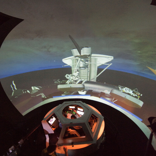
I have a prepared response, with foreseen and known knowledge, regarding modeling Earth’s atmosphere and outer space. Simulations employ sophisticated computation models to mimic Earth’s atmosphere’s wind flow, temperature variation, and chemistry. For space explorations, these simulations aid in predicting spacecraft reentry heating, spacecraft life, and possible ecological consequences. Using powerful CAD instruments, Mars and Titan moons,” atmospheric conditions, and computer-aided designs can also be analyzed. These computer-based simulations are called dynamic models, which serve various purposes, including enhancing safety, predicting numerous possible outcomes, and assuring the success strategies for the missions sought. They are essential for developing and monitoring the Earth’s environment and exploring the universe.
Now, collaboration is possible in real-time through virtual environments, allowing distinct groups to work in parallel. Users can use virtual reality (VR), augmented reality (AR), and advanced cloud services to participate in interactive 3D environments modeled after the real world or magically designed from scratch. These environments are helpful for engineering, medicine, and even teaching, especially those dealing with 3D visualization and interactive troubleshooting.
The following are the parameters of a collaborative tool with required latency, bandwidth, and hardware VR/AR requirements:
Latency: Latency should be less than 20 ms for smooth interactions. Anything above that may result in some delays.
Bandwidth Requirements: For high-quality video and 3D rendering, a minimum of 10 Mbps is required, and it should be even higher for more complex environments.
VR/AR Hardware: Devices like the Oculus Quest 2 or HoloLens 2 are needed for effective blended collaboration.
Platform Scalability: The system is expected to handle large numbers of users with little to no decrease in performance: over 50 users in a single session.
Data Security: Secure collaboration data requires basic security, including end-to-end encryption and access control.
Cross-Platform Compatibility: Support for multiple devices, which includes desktop, mobile, and VR headsets, ensures wider reachability.
These platforms and tools integrate greater efficiency and productivity into the workflows of the geographically dispersed modern world.
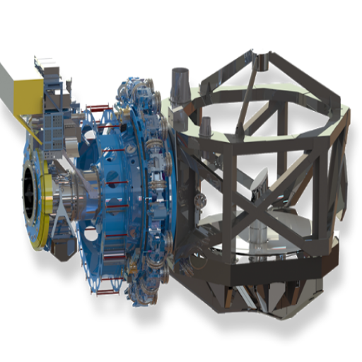
NASA uses CAD software to improve the accuracy and efficiency of its modeling, testing, and analysis of telescopes and satellite systems. Engineers use CAD systems for precise implementation to build 3D models of spacecraft components and subsystems. When creating these environment models, simulations of thermal and structural loads can be tested to assess how the component will behave in practical scenarios. Using CAD and other technologies like finite element analysis and CAD-based prototyping, NASA improves the speed, cost efficiency, and dependability of new space instruments.
I greatly emphasize new technology integration and advanced design processes while using sophisticated CAD tools to meet the set accuracy of next-generation satellites. These methods help me to solve problems like weight versus performance versus structural integrity. I also calculate temperature extremes, vibrations, and other environmental conditions the satellite must endure. Employing precision engineering techniques alongside real-world testing ensures that all satellites, covering communications, Earth observation, and other tasks, fulfill mission objectives with guaranteed reliability and efficiency.
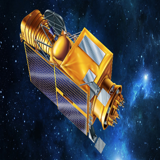
Computer-aided design (CAD) has made telescope construction much easier, and astronomy has advanced significantly. This is due to CAD’s capacity to improve complex design processes and precision while incorporating intricate engineering needs. CAD has revolutionized the work of scientists and engineers, who can now model telescopes in 3D, visualize their functionalities in real-world scenarios, and optimize their parts to their fullest potential.
One of the principal benefits of CAD is its ability to ensure alignment and reduce aberrations in complex optical systems. For example, CAD systems are required to include exact degrees of curvature and placement for the mirrors in modern telescopes. For example, the James Webb Space Telescope’s CAD software sets the primary mirror diameter (6.5 meters for the JWST) and surface accuracy (in nanometers). The level of detail achieved per mirror ensures unparalleled image quality.
The implementation of CAD also provides exact specifications for the telescope’s mechanical components. Engineers can model structural loads, thermal expansions, or even vibrations to confirm stability during operations. Due to the high atmospheric distortions, ground-based telescopes must harness real-time correction. This is possible due to the design of adaptive optics systems and their high-precision CAD tools, which consider the speed of the reaction and actuator position.
In addition, CAD software allows sophisticated materials to be used in telescope structures, such as superlight beryllium mirrors and carbon fiber-reinforced polymers chosen for their strength-to-weight properties. CAD simulations ensure that the telescope, like space instruments, can survive harsh environments of -223°F to 180°F while functioning normally.
Engineers can make phenomenal advancements in astronomical exploration by centralizing and streamlining telescope construction. These technological advancements have led to telescopes capable of viewing exoplanets, faraway galaxies, and other extraordinary universal spectacles, all while providing incredible detail and precision.
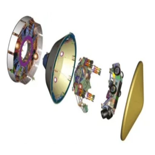
CAD software significantly helps with NASA’s rover projects by refining precision and increasing productivity. It enables the construction of sophisticated 3D models and guarantees that the parts undergo thorough checks on whether they work and can be depended on before mass production starts. This reduces mistakes, saves money during manufacturing, and speeds up the development process. In addition, CAD assists in team collaboration through design data sharing, which is vital in producing rovers that can endure the harsh conditions on Mars. With these tools at their disposal, NASA can broaden the scope of ingenuity possible in planetary exploration. Through optimizations, CAD Software helps NASA Mars rover projects with precision, accuracy, and productivity. Engineers build complex three-dimensional models.
Before production, CAD ensures all parts undergo proper inspection, functionality, and dependability tests. This step prevents mistakes, lowers production costs, and speeds up development time. CAD also helps share data across teams, thus assisting collaboration during projects. This is very important for producing rovers that can tolerate the harsh conditions of Mars. With the help of these tools, NASA is constantly innovating in planetary exploration.
Constructing Mars rovers requires several essential steps that convert ideas from digital models into real-life models that survive outside the Earth. Below are tips about processes and brief answers:
What are the primary goals during the prototyping phase?
The main aims include confirming that the parts are working, proving their durability, and determining whether they function under Mars conditions of cold, low gravity, and high radiation.
What key technical parameters are considered?
Weight: Usually 300-1000kg, depending on the mission’s load.
Power Supply: Solar systems with 110-140W and nuclear power for extended missions.
Temperature Tolerance: Ability to function at -125 C to 20 C on Mars.
Mobility: Ground level clearance of 5-10 inches and movement speed of 0.1 to 0.2 km/h per hour.
Communication: An antenna capable of receiving data over millions of kilometers and transmitting with a high gain.
Autonomy: Real-time obstacle/route identification and tracking enabled with AI systems.
Functionality testing: How is it done?
Parts are placed in specialized chambers that simulate Martian environments. The tests include thermal-vacuum trials, vibration testing for launch conditions, stress tests on material durability, mobility in pavements and vehicles, and Mars-like terrain for walking.
Each parameter is methodically addressed to ensure a successful deployment to Mars and the rover’s long-term functionality. Engineers often spend days or weeks at a time on the rover.
To maximize rover designs for space travel, these crucial areas must be optimized to work and be dependable in harsh and erratic conditions:
1. What materials are utilized?
Rovers are manufactured with new lightweight and strong materials, including titanium alloys, aluminum, and carbon fiber. These materials underwent careful selection due to their strength over weight ratio, resistance to corrosion, and capability to resist severe temperature changes (from 125 degrees Celsius below zero to 20 degrees Celsius above on Mars). Specially designed thermal coatings and insulating layers help reduce electronic heat loss and improve their well-being.
2. How are mobility obstacles solved?
Rovers have wheel systems specially designed for their particular rough job. Wheels are often produced from pliable aluminum or titanium and have cleats and other textures that enable them to move better on soft surfaces, rocky areas, or dusty places. Suspension systems, like the rocker-bogie used in robotics and didactic toys, distribute the weight evenly and enable the six-wheeled vehicle to climb slopes as high as 45 degrees. Other systems, like treaded moving parts and improved grappling devices, may be utilized for lunar or icy ventures.
What is the source of Energy and Power Management?
Multi-mission Radioisotope Thermoelectric Generators (MMRTGs) power long-duration missions, while solar panels are used for lighter designs. These instruments typically supply power for long-duration missions. Lithium-ion and rechargeable Nickel-Metal Hydride batteries store energy. The advanced power systems and solar arrays provide a reliable solution, as they can generate up to 900-1400 watt-hours per sol at Mars in ideal conditions. MMRTG’s solar power can provide constant energy and over 100-watt output for decades.
How is Functionality Tested?
Mars missions are put through vibration tests that simulate launch stress and mobility tests utilizing soil simulants. The JPL Mars Yards are used with hyperbarric chambers that recreate extreme temperatures and thin atmospheres. Several systems can provide autonomy and navigation capabilities with the help of sensors, LiDAR, and state-of-the-art AI-powered real-time obstacle detection systems.
Engineers have combined advanced mobility solutions with robust material construction alongside extensive testing procedures to improve the design of rovers for better adaptability to extraterrestrial missions. This guarantees success for the mission and ensures maximum efficiency during extraterrestrial exploration.
Using various interoperability tools, NASA employs a mix of CAD software packages via standardized file formats and collaborative platforms. Engineers use formats like STEP and IGES to facilitate inter-software data transfer and preservation of design. Furthermore, NASA utilizes proprietary software integrations and Application Programming Interfaces (APIs) to automate the synchronization of design changes from one platform to another. Moreover, unified workflows and cloud-based solutions enable collaboration among multidisciplinary teams while ensuring compatibility and efficiency throughout the spacecraft development process.
To put into place a seamless CAD environment for space projects, one must resolve a few issues of great importance:
Interoperability Between CAD Software
Implement standardized file exchange formats such as STEP (ISO 10303) and IGES.
Support advanced file formats like Parasolid or JT for complex geometric precision.
API and Custom Integrations
Create and deploy APIs to allow for the synchronization of design changes across platforms.
Automate data conversion and communication with the use of custom middleware.
Collaboration Tools and Platforms
Implement PDM/PLM systems like Windchill or Teamcenter, enabling cloud-based collaboration with version control.
Enable real-time co-editing capabilities for teams distributed across the globe to enhance teamwork.
Accuracy and Verification
Assign tolerances for dimensional accuracy of ±0.01 mm for critical components of the device.
Use the integrated verification tools to confirm the accuracy of the imported or exported designs.
Workflow Standardization Set and govern the engineering standards for file organization, naming conventions, and metadata.
Set up standard operating procedures for frequently performed activities to enhance productivity and ensure consistency.
Through these measures, with the support of modern technologies, businesses can develop a CAD environment that enhances operational productivity while guaranteeing integration and precision throughout the entire spacecraft development process.
The engineering team can utilize several tools simultaneously without sacrificing effectiveness using multi-software integration. The following practices and recommendations can assist with achieving the desired outcome:
Interoperability and Compatibility
Make sure that all software applications possess the ability to use standard file types such as STEP (stp), IGES (igs), and Parasolid (x_t) to enable data transfer with ease.
Use middleware or proprietary APIs to bridge gaps between incompatible systems for optimized data transfer.
Automated Data Synchronization
Put in place two-way synchronization processes to ensure that changes made on one site are automatically updated on all other sites without needing to be done manually.
Set up software with version control systems like PDM/PLM tools to reduce data contention and enhance collaboration.
Performance Optimization
Obtain high-performance computing hardware supporting resource-demanding multimodal integrations to ensure smooth operation.
Adjust the network bandwidth parameters to decrease the lag time during large file transfers between systems. Aim for a minimum of 1 Gbps bandwidth for internal transfers.
Standardized Workflows
Standardize and document workflows to decrease redundancy and mistakes while moving from one software to another.
Each team member interoperability protocols to help achieve unchanged quality.
Security and Data Integrity
Share sensitive design data among tools using encryption standards, such as AES-256.
Data must be regularly backed up to secure locations to prevent losses during data integration.
Sharing data inter-organizationally with external parties can be risky; however, by following these protocols, companies can achieve fully integrated CAD processes and ensure that every engineering project is completed with maximum efficiency and accuracy.
Leading CNC Metal Machining Provider in China
A: NASA extensively uses Computer-Aided Design (CAD) software in aerospace design for various purposes. It enables engineers to create detailed 3D models of spacecraft, satellites, and other space-related components and systems. CAD is crucial in designing and developing NASA projects, allowing for precise measurements, simulations, and analysis before physical prototypes are built.
A: NASA uses various CAD software packages, including SolidWorks and Creo. These powerful tools are essential for aerospace design and engineering. While NASA doesn’t exclusively use one software, many engineers and contractors use SolidWorks due to its versatility and robust analysis tools. The choice of software often depends on the specific project requirements and the preferences of different teams within the organization.
A: CAD software enhances collaboration in NASA projects by providing a platform for engineers and designers to collaborate. It allows team members to share designs, make real-time modifications, and collaborate on complex projects regardless of their physical location. This collaborative aspect is crucial for NASA, which often works with international partners and distributed teams across different facilities.
A: NASA uses CAD and simulation software to conduct various analyses on spacecraft and components. This includes stress analysis, thermal analysis, and fluid dynamics simulations. Using CAD models as a basis for these simulations, NASA can predict how designs will perform under different conditions, such as the extreme temperatures and pressures of space, without costly physical testing at early stages.
A: CAD software significantly contributes to the safety and reliability of NASA’s space missions by allowing for detailed design analysis and virtual testing. Engineers can use CAD models to identify potential design flaws, conduct stress tests, and optimize components for maximum performance and durability. This meticulous virtual prototyping process helps ensure that all systems meet the stringent safety requirements for space travel before any physical construction begins.
A: Yes, Python is often used in conjunction with CAD software at NASA. While not a CAD tool, Python is a powerful scripting language that can automate tasks, process data, and extend the functionality of CAD software. NASA engineers may use Python to create custom tools, analyze CAD data, or integrate CAD processes with other software systems, enhancing the overall efficiency of their design workflow.
A: NASA’s use of CAD software is similar to that of the broader aerospace industry, with some key differences. Like significant aerospace companies like Boeing, NASA uses CAD for design, analysis, and simulation. However, NASA often pushes the boundaries of CAD usage due to space exploration’s unique and extreme requirements. The agency may develop custom plugins or software interfaces to address specific needs that commercial off-the-shelf solutions don’t cover.
A: The use of CAD software offers significant cost-effectiveness benefits for NASA. By enabling detailed virtual prototyping and testing, CAD reduces the need for expensive physical prototypes in the early design stages. It also helps optimize designs for performance and manufacturability, potentially lowering production costs. Additionally, quickly iterating designs and catching errors early in the process can save substantial time and resources throughout a project’s lifecycle.

Manufacturing processes are quite complex, and the choice of a production method is directly related
Learn More →
There are two major manufacturing methods for producing plastic prototypes that most people find useful
Learn More →
As a person involved or interested in the design and production of plastic components, it
Learn More →