

Manufacturing processes are quite complex, and the choice of a production method is directly related
Learn More →
An accurate understanding of the K-factor is essential for effective and precise machining in sheet metal bending. This specific value is necessary in determining the behavior of the metal during bending, such as the impact it will have on bend allowance and bend deduction. For fabricators, learning the K-factor involves more than just a tool; it is a conduit for improved operational efficiency, reduced material losses, and better quality. In this workbook, we will explain what the K-factor is, how it is utilized throughout the fabrication process, and tips to help you improve your craft. This guide will prepare any level of individual, whether a novice or a professional, in the metalworking industry in need of knowledge that will permit them to improve their techniques in bending and aid in optimizing work processes.
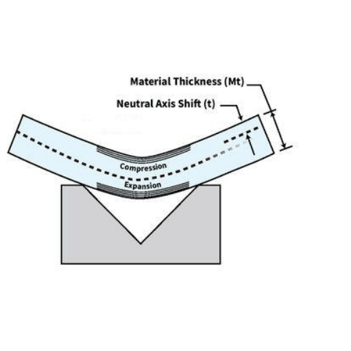
In the K-factor of sheet metal bending, which is a constant, the neutral axis shift in the material is compared against the thickness of the sheet. The neutral axis during bending is the region of the metal that is bent without stretch or compression. For specific and accurate results in fabrication, the K-factor can be considered to be most important when an accurate computation of bend allowances is required. Its value is usually between 0 and 0.5, affected by the material properties such as type, thickness, and bend radius. Grasping the K-factor is important for maintaining constancy and accuracy of bend dimensions.
The K-factor denotes the position of the neutral axis relative to the thickness of the material being bent. It also indicates how much material is stretched or compressed when bending occurs. Understanding this factor precisely helps in making calculations of bend allowances which enhances a metal’s fabrication accuracy and its repeatability. The K-factor’s value changes according to the material attributes, thickness, and radius of the bend, which is why it is so important to measure and implement this factor as accurately as possible.
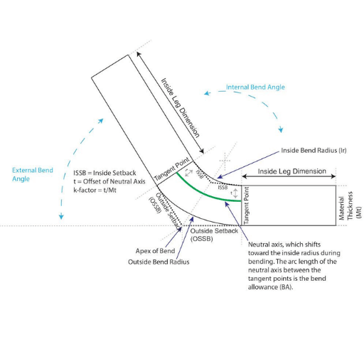
The K-factor is concerned with the location of the neutral axis in the bending operation. The neutral axis is defined as the axis of the sheet metal where there is no tensile or compressive strain while bending occurs. The K- factor is the ratio of the distance from the neutral axis to the inner bend surface, and the thickness of the material. Knowing the K factor enables the engineer to estimate the position of the neutral axis and adjust bend allowances accurately, thus controlling the dimensions of the finished part with high accuracy.
The consideration of the K-factor when determining bend allowance is crucial since it directly affects the estimate of total sheet metal needed to create a bend. Bend allowance is the neutral axis’s arc length within a bend, and it is impacted by the K-factor, material thickness, bend angle, and radius.
Take, for example, a conventional steel sheet that has a thickness of 1.5 mm, a bend angle of 90°, and an internal radius of 2 mm. The K-factor is crucial in determining the appropriate bend allowance through the following formula:
“Bend Allowance (BA)=(π/180)(Bend Angle)(Radius + K-factor * Thickness)”
The accuracy of this equation is dependent on the correct value of the K-factor that takes into consideration the factors of the material’s mechanical properties and the method of bending used. For example, ductile materials like aluminum will almost always have a higher K-value compared to high-strength steel. For most materials, the average range for the K-factor is about 0.5 and 0.3 but in some extreme conditions, it might lie outside that range.
The most recent developments in CNC bending technology emphasize the need to modify the K-factor based on practical testing and simulations. Take, for example, experimental results regarding stainless steel that indicate the best K-factor under standard conditions is 0.4, which guarantees the deviations for the estimated dimensions do not exceed ±0.1 mm. This modification improves the precision of bend allowance computations and produces repeatable outcomes in sheet metal operations.
Knowing as well as correctly manipulating the K-factor helps the manufacturers reduce the loss of materials, increase productivity, and meet the predetermined tolerances in the end product.
The k-factor values in metal sheet bending processes can be influenced by several characteristics.
Controlling these factors guarantees better-bending results and makes the process of sheet metal manufacturing substantially more efficient.
K-factor calculators simplify the calculations for bending sheet metals to a great extent. They are programmed to return approximate K-factor values for given conditions, where specific parameters such as material type, thickness, bend radius, and angle of bend are entered. A good calculator guarantees accuracy, consistency in bends, and a significant reduction in waste. This is extremely helpful for improving manufacturing productivity.

The K-factor is important for determining accurate bend deductions, which are essential for the accurate flat pattern calculation of a given sheet metal part. Bend deduction is when the total flange lengths (inside dimensions of the part) is subtracted from the flat pattern length. Knowing how the material behaves during bending, the K-factor aids in determining the necessary amount of deformation to match the design intent.
As an example, for aluminum where the bend radius is equal to the material thickness, K-factors usually fall within 0.33-0.5 depending on the alloy and temper. But for steel which has a K-factor value that may range between 0.4-0.5 due to the increased strength and resistance to deformation. Changing the K-factor value ensures precise math calculations for bend allowance and bend deduction that will minimize trial-and-error on the floor.
Precise calibration of the K-factor influences the generation of flat patterns in the CAD computer software package. Many contemporary design applications such as SolidWorks and AutoCAD use the K-factor as one of the parameters for flat pattern generation. This integration optimizes the material usage while ensuring proper seamless assembly of the components. For more intricate geometries or high-accuracy applications, using inappropriate K-factor values can cause misalignment of parts, unintended material stress, and other problems that are expensive and time-consuming to rectify. Properly researched and validated K-factor values expedite this process and enhance accuracy in fabrication.
To make sure that there is accuracy while designing a sheet metal, it is important to compute the bend allowances and material properties with precision. Use the K-factor and other vital values as constants to enhance uniformity and minimize mistakes. For the correct modeling and checking of components before production, use CAD software. Frequently review the designs; simulations and prototypes should be checked to avoid misalignment and deformation of materials. Always check standards and regulations for best practices in manufacturing.
Material efficiency remains one of the most important aspects of contemporary production as it affects production costs and ecological issues. Research suggests that sophisticated CAD programs and production methods can decrease material consumption by as much as thirty percent. Automated nesting tools, for instance, optimize the cutting of raw material sheets into parts by calculating the best possible arrangement to avoid offcuts. Moreover, additive manufacturing and other forms of generative design let engineers build structures that are not only lightweight but are also bound to use the least material possible, thus, reducing waste even further.
As an example, some companies that practice generative design coupled with Artificial Intelligence material optimization report savings of up to twenty percent on material expenses. Also, closed-loop manufacturing and recycling programs guarantee that no material goes to waste, which subscribes to the circular economy ideology. Companies adopting these methods are able to save money while also minimizing their environmental impact, which is essential for sustainable development.
The K-factor is a crucial value in sheet metal design, as it refers to the position of the neutral axis of the bending sheet about the thickness of the sheet. It is critical for precise calculation of bend allowances as well as accuracy in fabrication. Some typical K-factor values for common materials affected by material type, thickness, and bending processes are below.
It is crucial to mention that specific factors, including the type of bending (air bending, bottom bending, or coining), tooling, and bend radius, can affect these values. For exacting tasks, companies usually resort to empirical trials or sophisticated simulation software to establish the most precise K-factor for their operating conditions.
The K-factor is impacted as a result of the material’s properties because the K-factor changes with the material’s behavior during bending. Some clear examples are:
This understanding allows manufacturers to estimate the K-factor and its desired value with quite a good level of accuracy for optimal bend calculations.
For SolidWorks incorporating the K-factor into Sheet Metal tools, do the following:
Access the Sheet Metal Settings:
Open the part file in SolidWorks. Make sure that the Sheet Metal feature is activated.
In the Command Manager, go to the Sheet Metal tab or go through the Insert function.
Set the K-Factor:
Open the Sheet Metal Parameters dialog box while making the part or when editing the existing sheet metal feature.
Identify the portion that has the allowance for bend or K-factor.
Insert the required K-factor that corresponds to the properties of the material and design needs.
Apply to Bends:
K-factors need to be consistent at the various bends in the model. SolidWorks uses this value to adjust the flat pattern dimensions.
Generate a Flat Pattern:
Use the Flatten tool to see a preview of the flat pattern that has K-factor modifications.
With correct K-factor information provided in SolidWorks, Sheet Metal features are automatically assigned predetermined values to allowances for bends so that the flat pattern for the part is exact for production requirements. As a best practice, verify your data against material information and bend rules to minimize gaps.
When incorporating the K-factor within CAD systems, I make it a point to make sure that material specifications and their corresponding thicknesses are checked prior to assigning a value. I invariably confirm the K-factor against empirical test data to reduce discrepancies in flat pattern sizes. Moreover, I validate the generated flat patterns against the manufacturing tolerances so that they can be used in the production processes. This verification improves accuracy and efficiency throughout the CAD design and fabrication workflow.
The Y-factor adjusts for the physical effects that occur in a material during bending operations and is used specifically in the context of sheet metal bending. It is distinctly different from the K-factor, which is solely dependent on the material’s neutral axis location inside the workpiece. It is predominant from empirical tests and is widely used in CAD packages for automated flat pattern design. This adjustment increases accuracy in manufacturing by modeling how the material stretches or shrinks under certain conditions.
Selecting the K and Y factors for sheet metal bending is often a matter of accuracy needed and the phase within the design and manufacturing process. The K factor which indicates the location of the neutral axis as a ratio of the material’s thickness, is recommended for generalized calculations where the behavior of the material under stress is uniform and constant. Thus, it is suitable for standardization in the early stages of design or when a material with well-defined characteristics is used.
However, application of the Y factor is preferred when higher precision is required, especially in cases of more intricate bend geometry or less conventional materials. Y accounts for both the elastic and compressive behavior of the material and thus is more flexible in nature. For instance, for bending higher tensile strength materials such as stainless steels and aluminum alloys, it is more beneficial to include bend allowance Y which accounts for specific material elongation. It has been proven that Y is necessary for achieving the least variation from target value in many high-precision fabrication processes, such as aerospace or automobile component manufacture, where the degree of tolerance on dimensions is very tight leading to functional failure or assembly difficulties if the sizes and shapes are inaccurate.
When determining which factor to use, consider the required precision – The k-factor works for basic designs while the Y-factor is better for highly detailed modeling and production which involves complex material properties. These two factors are interdependent and can be integrated into CAD programs to improve estimate accuracy at various points in the product life cycle.
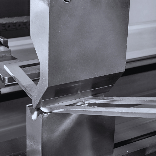
The K factor is a critical parameter when adjusting the press brake for bending processes. If manufacturers know how the neutral axis and the material elongation change with bending, they can accurately reduce errors for precise outcomes. Research indicates that using an accurate K factor improves bend accuracy from 5% to 20% in severe cases such as bending HSLA (High Strength Low Alloy) steel or Aluminum.
To set a press brake, a user must input material thickness, tensile strength, and material type. For thinner materials, the bend allowance is usually greater, which means, the K factor needs to be adjusted up by values of 0.3 to 0.5. On the other hand, thicker materials or those with greater internal tensile properties will require a K factor adjustment closer to 0.2. Many modern CNC press brakes have these values incorporated in the programming making the machines more user-friendly while reducing the guesswork needed on the shop floor.
Moreover, standardizing bending radii and setup times for tooling reduces the complexity of the K factor application. V-die tools set to the thickness of the sheet metal give optimal results as wrong tooling can cause the bend angles to be so cantilevered, that geometric tolerances can no longer be maintained. Moreover, modern simulation software can aid in determining deviations from the expected outcome even before the parts are made, saving material and downtime.
For massive production or projects with very tight tolerances, combining empirical K-factor information with advanced press brake technology guarantees quality. The implementation of such practices not only assures accuracy but also enhances the efficiency of production, which enables manufacturers to easily comply with industry requirements.
Inaccurate bends may arise from differences in K-factor application or tooling setup. When diagnosing these problems, it is important to evaluate the causes of bend actions. Changes in material thickness and strength can impact the K-factor and create strange surprises. With the help of material testing before the cutting process, the manufacturer can prove that the K-factor is close to the attributes of the material.
One more problem that makes processes of estimation widely differ is a wrongly set tool. The wrong set of a punch tip made the radius or V-die width not appropriate for the material thickness results in rough bends or roughness. Research suggests that V-die openings should typically range from 6 to 12 times the material thickness to make sure they form the required bends correctly. For instance, a V-die opening of 14-16 mm is available for bending a 2 mm sheet.
Bending accuracy can be compromised by the changing temperature of the machines, mechanical wear, and other factors. Equipment like press brakes, for example, are of specific sensitivity to their conditions of operation, and it is usually observed that from time to time equipment is calibrated for a predecessor force output. The force application sensitivity is sometimes equipped with load sensors and automatic angle correction systems that help identify where those factors come from and actively.
New simulation tools under modern technology bring added benefits for problem-solving. By providing accurate K-factor values, material characteristics, and tooling configurations, simulations can estimate possible bending mistakes within the design phase. Research indicates the use of simulation software in high-volume manufacturing reduces scrap rates by up to 30 percent.
Furthermore, springback behavior needs careful observation as well. More elastic materials, like aluminum, have a larger amount of springback which needs careful overbending. Digital protractors or laser-based measuring instruments allow post-bending fine-tuning of angles to ensure compliance with post-driven dimensional tolerances.
Through a mixture of empirical testing, equipment calibration, and advancements in technology, the uncertainties with K-factors can be solved, ensuring a high level of production consistency with set standards and quality.
A: It is the ratio of the position of the neutral axis to the material’s thickness in the bending of sheet metal. It is relevant in allowance of bend calculation and in estimating the dimensions of the fused component. The notion of k -factor is notable while working on metal sheet fabrication accuracy and making certain that the end product is to the standards.
A: For this, we must take the type of material, its thickness, and the radius of the inner bend all into account. The equation is k = t / T, where t is the distance from the neutral axis to the inside edge of the bend, and T is the thickness of the material. This is useful in assessing the degree of stretching or contraction of the material during the bending process.
A: Different factors, such as the type of material, its thickness, radius, and angle of the bend, and the method of bending can impact the k-factor. Also, the stem properties of the material, like their hardness and ductility, affect the k-factor. Other materials behave differently during the bending process and greatly impact the k-factor value.
A: A bend radius has a considerable impact on compressions and stretches applied to the material needing to be folded, making it equally influential in impacting k-factors. An increase in the k-factor will lead to movement of the neutral axis which also slightly increases the radius bend of the material. Accurate bend radius measurement is crucial for precise bend calculations and determining the length of the neutral line.
A: The k factor is used along with the thickness of the material, inside bend radius, and the bend angle. The formula is: Bend Allowance = (π * (R + kT) * A) / 180, where R is the inside bend radius, k is the k-factor, T is the material thickness, and A is the bend angle in degrees. It helps calculate the necessary sheet metal for the bend, thus guaranteeing exact flange lengths and total dimensions of the part.
A: Softer and easier-to-bend materials, such as aluminum, have lower k-factors than harder materials like stainless steel. Furthermore, the k-factor for a certain material is dependent on its ductility, work-hardening features, and grain structure. All of these factors need to be taken into account when estimating bend allowances for precise sheet metal fabrication.
A: There are several options for tools and software that assist with k-factor estimation and bend calculations. Some CAD applications, such as CATIA, have automatic sheet metal modules that calculate the required bend allowance. There are also some mobile apps or websites that cater specifically to metal sheet fabrication. Some manufacturing services, like SendCutSend, help their clients find the correct dimensions of the bend from their sheets and use their own calculated tools to do so.
A: The neutral axis’s location in a sheet metal bend is directly proportional to the k-factor. The neutral axis is that hypothetical line in the body that undergoes zero compressive and tensile forces when volumetric deformation is performed. The k-factor is the ratio of the distance from the inside of the bend to the neutral axis, over the thickness of the material. Knowing this information is important in the measurement of the neutral line’s length and the corresponding size of the bent part.
1. Spring-Back Effects Analysis and Evaluation on Steel Sheet Metal During Bending Operations
2. Title: The Influence of Punch Radius and Angle on the Bend Angle through Air V-Bending of Sheet Metal.
3. Optimization of TIG Welding Process Parameters on 304 Austenitic Stainless Steel Sheet Metal using Fuzzy Logic Based Taguchi Method.
4. Leading Sheet Metal Fabrication Services Provider in China

Manufacturing processes are quite complex, and the choice of a production method is directly related
Learn More →
There are two major manufacturing methods for producing plastic prototypes that most people find useful
Learn More →
As a person involved or interested in the design and production of plastic components, it
Learn More →